


ENGINEERING MANUAL OF AUTOMATION CONTROL
BUILDING AIRFLOW SYSTEM CONTROL APPLICATIONS
290
M12215
SUPPLY
AIR
SUPPLY
AIR TO
LAB
GENERAL
EXHAUST
AIR
EXHAUST
AIR
DAMPER
ACTUATOR
OR
AIR VALVE
AIRFLOW
SENSOR
SUPPLY
AIR TO
CORRIDOR
VELOCITY
SENSOR
DAMPER
ACTUATOR
OR AIR
VALVE
AIRFLOW
SENSOR
DAMPER ACTUATOR
OR AIR VALVE
AIRFLOW
SENSOR
LAB AIRFLOW
CONTROLLER PANEL
OR
SASH
SENSOR
LABORATORY PRESSURIZATION
Constant supply airflow often is not capable of constant space
pressurization in research laboratories because of the use of
constant face velocity fume hoods and the use of other variable
exhausts. To accomplish containment and prevent excessive
pressurization requires some form of volumetric air flow control
(air flow tracking) or control of differential pressure within the
lab space (direct pressure control).
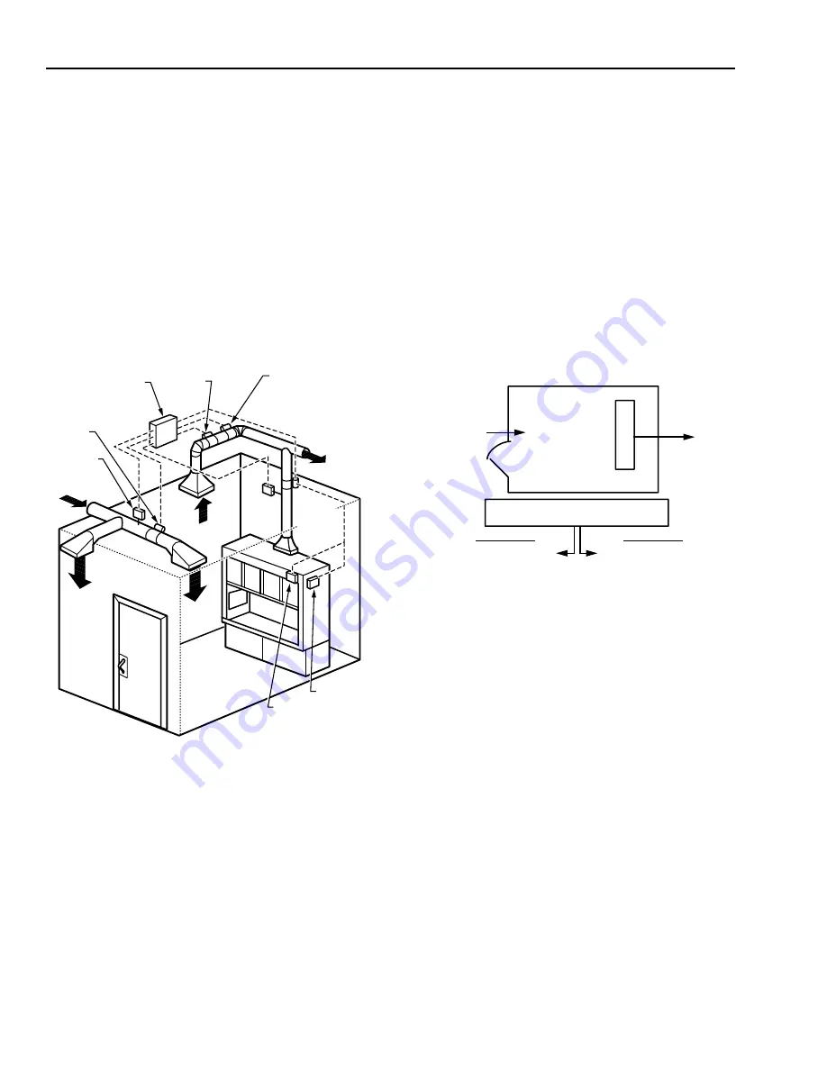
Airflow tracking (Fig. 46) measures all exhaust and supply
airflows and maintains a relationship between the total exhaust
and total supply. For space pressurization to be negative relative
to adjacent spaces, the total exhaust must exceed the total supply.
The difference between exhaust and supply airflows (offset)
should be a fixed quantity for an particular space to keep the
pressurization constant. A constant percentage offset value is
sometimes used.
If future flexibility and changing lab configurations are
important considerations, then flow sensor location, duct size,
supply airflow rate, and control system design should all include
capability to be modified in the future.
A characteristic of airflow tracking is stability of the system
in the face of breaches to the lab envelope. This is most often
lab door openings. In a laboratory maintained at a negative
pressure, the space static pressure increases and the air velocity
through all openings drops significantly when a door opens.
Figure 47 shows a laboratory example with a single fume hood,
a single door 36 in. wide x 80 in. high (20 ft2), and a crack area
estimated at 0.5 ft2. If the fixed airflow tracking differential is
200 cfm, the average velocity through the cracks would be 400
fpm which is more than adequate for containment. However,
when the door opens, the average velocity in this example
decreases to 9.8 fpm which is marginal to inadequate for
containment.
CRACK AREA = 0.5 FT 2
SUPPLY
800 CFM
DOOR
2
20 FT
FUME HOOD
EXHAUST
1000 CFM
DOOR CLOSED
= 400 FPM
DOOR OPENED
= 9.8 FPM
DIFFERENTIAL = EXHAUST – SUPPLY
= 200 CFM
C2637
VELOCITY = 200
20.5
÷
VELOCITY = 200
0.5
÷
Fig. 46. Airflow Tracking Control.
Airflow sensors located in all supply and exhaust ducts
provide flow signals which can be compared by a controller.
Sensor locations must meet the manufacturers minimum
installation guidelines, such as velocity range and length of
straight duct before and after the sensor, to ensure accuracy.
Materials and finishes for sensors in exhaust ducts exposed to
corrosive fumes must be carefully selected.
Fig. 47. Airflow Tracking Example with
Door Closed and Opened.
However, the ability of the tracking system to quickly (usually
within several seconds) react and compensate for door openings
and other breaches is a positive characteristic of this control
method.
Supply duct pressure and building pressurization control are
simpler and more stable with airflow tracking because they are
less affected by this type of unexpected upset. The supply duct
pressure control remains stable due to fewer disruptions.
Building pressurization, defined as the difference between total
air leaving the building and the total air entering, remains the
same.
Direct pressure control (Fig. 48) provides the same control
function as airflow tracking but its characteristics are quite
different. Direct space pressurization control senses the
differential pressure between the space being controlled and a
reference space which is usually an adjacent space or hallway.
Summary of Contents for AUTOMATIC CONTROL
Page 4: ...ENGINEERING MANUAL OF AUTOMATIC CONTROL iv ...
Page 6: ...ENGINEERING MANUAL OF AUTOMATIC CONTROL vi ...
Page 11: ...ENGINEERING MANUAL OF AUTOMATIC CONTROL CONTROL FUNDAMENTALS 1 CONTROL SYSTEMS FUNDMENTALS ...
Page 12: ......
Page 46: ...ENGINEERING MANUAL OF AUTOMATIC CONTROL CONTROL FUNDAMENTALS 36 ...
Page 66: ...PSYCHROMETRIC CHART FUNDAMENTALS 56 ENGINEERING MANUAL OF AUTOMATIC CONTROL ...
Page 128: ...ENGINEERING MANUAL OF AUTOMATION CONTROL ELECTRIC CONTROL FUNDAMENTALS 118 ...
Page 158: ...MICROPROCESSOR BASED DDC FUNDAMENTALS 148 ENGINEERING MANUAL OF AUTOMATIC CONTROL ...
Page 210: ...ENGINEERING MANUAL OF AUTOMATIC CONTROL BUILDING MANAGEMENT SYSTEM FUNDAMENTALS 200 ...
Page 440: ...ENGINEERING MANULA OF AUTOMATIC CONTROL INDIVIDUAL ROOM CONTROL APPLICATIONS 430 ...
Page 516: ...ENGINEERING MANUAL OF AUTOMATIC CONTROL GENERAL ENGINEERING DATA 506 Notes ...
Page 517: ...ENGINEERING MANUAL OF AUTOMATIC CONTROL GENERAL ENGINEERING DATA 507 Notes ...
Page 518: ...ENGINEERING MANUAL OF AUTOMATIC CONTROL GENERAL ENGINEERING DATA 508 ...


