7B3-6 NEW PROCESS TRANSMISSION
DISASSEMBLY AND ASSEMBLY OF SUB-ASSEMBLIES
403 460
404
405
434 433
403.
404.
405.
433.
434.
460.
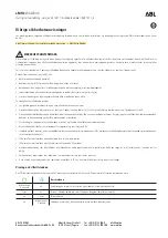
Snap Ring, Bearing to Shaft
Main Drive Gear Bearing
Main Drive Gear
Snap Ring
Pilot Bearings
Snap Ring, Bearing to Case
❖
*
❖
B-08861
Figure 6 — Main Drive Gear Components
MAIN DRIVE GEAR
D isassem ble (Figure 6)
1. Pilot bearings (434) and the snap ring.
2. Bearing to case snap ring (460).
3. Bearing to shaft snap ring (403).
4. Bearing (404).
JJJI C lean (Figure 6)
All parts in a suitable solvent.
(Do not spin the bearings dry).
Inspect (Figure 6)
1. Parts for damage and wear.
2. Oil the bearings and check for roughness.
A ssem ble (Figure 6)
1. Bearing (404).
• Press the bearing against the shoulder on the
shaft.
2. New bearing to shaft snap ring (403).
3. New bearing to case snap ring (460).
4. Pilot bearings (434).
• Use chassis grease to hold the bearings in
place.
MAINSHAFT
3.
4.
D isassem ble (Fig ure 7)
Slide the 3rd speed blocker ring (406) ofr.
Remove the snap ring and slide the 3rd and
overdrive synchronizer (407) off.
• Do not let the synchronizer come apart.
Remove the overdrive blocker ring and the overdrive
gear (409).
Speedometer drive gear (420).
• Press the retaining clip down.
ijUji
13
*
Tap the gear off.
Im portant
• Do not let the mainshaft fall to the floor.
5. Rear bearing (415) and the 1st speed gear (414).
• Remove the snap ring.
• Support the gear in a press.
• Press the mainshaft through the bearing and
the gear (figure
8
).
6
. Slide the
1
st speed blocker ring off.
7. Remove the snap ring and the 1st and 2nd
synchronizer (412).
• Do not let the synchronizer come apart.
8
. Remove the 2nd speed blocker ring and the 2nd
speed gear (410).
9.
Synchronizers (407 and 412) (figure
9).
• The synchronizer hub and sleeve are a select
fit, do not mix the parts of the two
synchronizers.
• Mark the hub and sleeve alignment for
reassembly.
• Push the hub out of the sleeve while holding
the springs and keys to avoid losing them.
Clean
All parts in a suitable solvent and air dry.
Im p o rtan t
• Do not spin dry the bearings.
Inspect
1. Gears for cracks, chipped gear teeth, and other
damage that could cause gear noise.
2. Thrust washers and bushings for damage and wear.
3. Related surfaces on the gears like thrust faecs and
bearing surface diameters.
4. The reverse sliding gear for a sliding fit on the
synchronizer hub without excess radial, or circular
play. If the sliding gear is not free on the hub,
inspect it for burrs on the ends of the internal
splines. Remove any burrs by honing as required.
5. Synchronizer sleeves for a sliding fit on the
synchronizer hubs, also, the hubs have to be a snug
fit on the mainshaft splines.
6
. Synchronizer springs and keys for looseness and
damage.
7. Brass synchronizer rings for excess wear and
damage.
8
. All gear teeth for excess wear.
9. Bearings and bearing surface for nicks, burrs and
wear.
10. Lubricate all roller bearings with light engine oil and
check for rough rotation.
A ssem ble (Figures 7 and 10)
• Coat all parts with transmission oil before installing
them onto the shaft.
1
. Synchronizers (407 and 412) (figure 9).
• Place the keys into the hub.
Summary of Contents for 1989 Light Duty Truck
Page 1: ...vr V Light Duty Truck Unit Repair Manual...
Page 2: ......
Page 11: ...GENERAL INFORMATION OA 5 Figure 8 RV Models...
Page 13: ...GENERAL INFORMATION OA 7 Figure 11 ST Models...
Page 18: ......
Page 44: ......
Page 76: ...1B3 18 R 4 AIR CONDITIONING COMPRESSOR N...
Page 114: ......
Page 162: ......
Page 176: ...4B3 14 91 2 INCH RING GEAR...
Page 192: ...4B5 4 DANA REAR AXLES Figure 4 Spreading the Differential Case Figure 7 Removing the Ring Gear...
Page 218: ......
Page 220: ...4B6 2 12 INCH RING GEAR ROCKWELL F 04734 Figure 1 Rear Axle Components...
Page 229: ...12 INCH RING GEAR ROCKWELL 4B6 11 SPECIAL TOOLS Special Tools...
Page 230: ...4B6 12 12 INCH RING...
Page 240: ...4B7 10 LOCKING DIFFERENTIALS SPECIAL TOOLS Special Tools...
Page 260: ...4C2 6 93 4 INCH RING GEAR FRONT AXLE Figure 16 Removing the Pinion Inner Bearing...
Page 273: ...T TRUCK FRONT AXLE 4C3 3 F 05785 Figure 1 Axle Components...
Page 291: ...K TRUCK FRONT AXLE 4C4 3 Figure 1 Front Axle Com ponents K 15 25 Models...
Page 293: ...K TRUCK FRONT AXLE 4C4 5 Figure 3 Front Axle Com ponents K35 Models...
Page 318: ...C4 30 K TRUCK FBOHT AXLE...
Page 334: ......
Page 361: ...2 5 LITER L4 ENGINE 6A1 5 Figure 3 Cylinder Head Manifolds and Components...
Page 363: ...2 5 LITER L4 ENGINE 6A1 7 F 05715 Figure 5 Block and Components...
Page 395: ...2 8 LITER V 6 6A2 3 Figure 1 Engine Lubrication Diagram...
Page 396: ...6A2 4 2 8 LITER V 6 Figure 2 Engine Lubrication Diagram...
Page 424: ...6A2 32 2 8 LITER V 6...
Page 427: ...I 4 3 LITER V 6 6A3 3 Figure 1 Engine Lubrication Diagram B 07857...
Page 451: ...4 3 LITER V 6 6A3 27 SPECIFICATIONS ENGINE SPECIFICATIONS F 6344...
Page 457: ...4 8 LITER L6 6A4 3 Figure 2 Lubrication Diagram Front View...
Page 460: ...6A4 6 4 8 LITER L6 C 1 107 112 fK 108 3 109 165 129 B 05056 Figure 5 Block and Components...
Page 490: ...Ml...
Page 493: ...V8 ENGINE 6A5 3 Figure 1 Lubrication Diagram 5 0L and 5 7L Engines...
Page 494: ...6A5 4 V8 ENGINE Figure 2 Lubrication Diagram 5 0L and 5 7L Engines...
Page 530: ...6A5 40 V8 ENGINE Figure 81 Exhaust Manifold 7 4L Engines Figure 82 Water Pumps and Components...
Page 571: ...6 2 LITER DIESEL 6A7 35 Figure 58 Vacuum Pump Installed...
Page 576: ......
Page 582: ...6C1 6 MODEL 1MEF CARBURETOR Figure 9 Monojet Model 1MEF...
Page 604: ...6C2 6 MODEL M4MEF CARBURETOR Figure 9 Model M4MEF...
Page 640: ...6C4 8 MODEL 700 THROTTLE BODY...
Page 652: ...nmm...
Page 672: ......
Page 693: ...DISTRIBUTORS 6D5 13 Figure 27 Testing the Pickup Coil Figure 28 Testing the Ignition Coil...
Page 696: ......
Page 698: ...7A1 2 700 R4 AUTOMATIC TRANSMISSION Figure 1 Case and External Parts J H 0 0 5 3 7 0 0 R 4 R 2...
Page 745: ...700 R4 AUTOMATIC TRANSMISSION 7A1 49...
Page 762: ...7A2 2 400 475 AUTOMATIC TRANSMISSION Figure 1 Case and External Parts H H 0021 400 R 3...
Page 773: ...400 475 AUTOMATIC TRANSMISSION 7A2 13 Figure 29 Internal Parts H H 0 0 4 3 4 0 0 R 2...
Page 797: ...400 475 AUTOMATIC TRANSMISSION 7A2 37 Figure 93 Control Valve Assem bly...
Page 803: ...400 475 AUTOMATIC TRANSMISSION 7A2 43 Figure 104 Bushing Replacement Procedure...
Page 808: ...J c I i sal...
Page 838: ......
Page 840: ......
Page 842: ......
Page 850: ...7B1 12 HM 290 MANUAL TRANSMISSION J i t i a x V L...
Page 856: ...7B1 18 HM 290 MANUAL TRANSMISSION...
Page 892: ...7B1 54 HM 290 MANUAL TRANSMISSION Figure 93 Special Tools...
Page 897: ...HM 117 TRANSMISSION 7B2 5...
Page 901: ...HM 117 TRANSMISSION 7B2 9 B 05180 Figure 17 Installing the 1st and 2nd Synchronizer...
Page 912: ...20 HM...
Page 924: ...7B3 12 NEW PROCESS TRANSMISSION SPECIAL TOOLS...
Page 927: ...BORG WARNER TRANSMISSIONS 7B4 3 Figure 2 77 mm Transmission and Components...
Page 940: ...i ii iii m i in m i...
Page 944: ...7D1 4 TRANSFER CASE FO 5688 Figure 3 NP205 Transfer Case...
Page 952: ...7D1 12 TRANSFER CASE...
Page 963: ...NEW PROCESS 241 TRANSFER CASE 7D2 11 Figure 17 Oil Pump Pickup Screen Doweled Case Holes...
Page 964: ...7D2 12 NEW PROCESS 241 TRANSFER CASE Figure 18 NP 241 Transfer Case Cut Away...
Page 978: ......
Page 981: ...BORG WARNER 1370 TRANSFER CASE 7D4 3 J...
Page 992: ...7D4 14 BORG WARNER 1370 TRANSFER CASE Figure 26 Installing the Rear Output Yoke...
Page 993: ...BORG WARNER 1370 TRANSFER CASE 7D4 15 Figure 27 BW 1370 Transfer Case...
Page 997: ......
Page 998: ...X 8937...