GENERAL ENGINE MECHANICAL 6A-9
B-05076
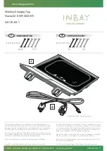
A. Press
B. A djustable Installer J-24086-9
C. Support Fixture J-24086-20
D. Connecting Rod Support J-24086-11
E. Pin Guide
F. Lock Ring
G. A djuster
H. Number Scale
• The piston must be installed with the piston
crow n in d e n t on th e sa m e s id e as th e
connecting rod bearing tang slots (figure 14).
2. Piston pin. Apply engine oil to the pin and push into
place.
3. Snap rings. Use J 29134-A (figure 15).
I?
Inspect
Snap rings for proper assembly. Rotate the
snap rings to make sure that they are seated
in their grooves.
Installing the Piston Rings (All Except 6.2 L)
M easure (Figures 4 and 16)
Figure 13— Installing the Piston Pin
• R em ove th e p is to n and c o n n e c tin g rod
assembly from the tool and check the piston
for freedom of movement on the piston pin.
Assembling the Piston
and Connecting Rod (6.2 L Engines)
*
A ssem ble (Figures 7, 14, and 15)
Tool Required
J 29134-A Piston Pin Clip Installer
1. Piston to the connecting rod.
Ring end gap as follows:
1. Select rings comparable in size to the piston
being used.
2. Slip the compressing ring in the cylinder bore:
then press the ring down into the cylinder bore
about 7 mm (1/4-inch) above ring travel. Be
sure the ring is square with the cylinder wall.
3. Measure the space or gap between the ends
of the ring with a feeler gage (figure 16).
4. Refer to “ Specifications” in the proper section
for correct gap.
5. If the gap between the ends of the ring is not
as specified, remove the ring and try another
for fit.
Fig u re 1 4 — Aligning th e Piston and C o n n ectin g Rod
Summary of Contents for 1989 Light Duty Truck
Page 1: ...vr V Light Duty Truck Unit Repair Manual...
Page 2: ......
Page 11: ...GENERAL INFORMATION OA 5 Figure 8 RV Models...
Page 13: ...GENERAL INFORMATION OA 7 Figure 11 ST Models...
Page 18: ......
Page 44: ......
Page 76: ...1B3 18 R 4 AIR CONDITIONING COMPRESSOR N...
Page 114: ......
Page 162: ......
Page 176: ...4B3 14 91 2 INCH RING GEAR...
Page 192: ...4B5 4 DANA REAR AXLES Figure 4 Spreading the Differential Case Figure 7 Removing the Ring Gear...
Page 218: ......
Page 220: ...4B6 2 12 INCH RING GEAR ROCKWELL F 04734 Figure 1 Rear Axle Components...
Page 229: ...12 INCH RING GEAR ROCKWELL 4B6 11 SPECIAL TOOLS Special Tools...
Page 230: ...4B6 12 12 INCH RING...
Page 240: ...4B7 10 LOCKING DIFFERENTIALS SPECIAL TOOLS Special Tools...
Page 260: ...4C2 6 93 4 INCH RING GEAR FRONT AXLE Figure 16 Removing the Pinion Inner Bearing...
Page 273: ...T TRUCK FRONT AXLE 4C3 3 F 05785 Figure 1 Axle Components...
Page 291: ...K TRUCK FRONT AXLE 4C4 3 Figure 1 Front Axle Com ponents K 15 25 Models...
Page 293: ...K TRUCK FRONT AXLE 4C4 5 Figure 3 Front Axle Com ponents K35 Models...
Page 318: ...C4 30 K TRUCK FBOHT AXLE...
Page 334: ......
Page 361: ...2 5 LITER L4 ENGINE 6A1 5 Figure 3 Cylinder Head Manifolds and Components...
Page 363: ...2 5 LITER L4 ENGINE 6A1 7 F 05715 Figure 5 Block and Components...
Page 395: ...2 8 LITER V 6 6A2 3 Figure 1 Engine Lubrication Diagram...
Page 396: ...6A2 4 2 8 LITER V 6 Figure 2 Engine Lubrication Diagram...
Page 424: ...6A2 32 2 8 LITER V 6...
Page 427: ...I 4 3 LITER V 6 6A3 3 Figure 1 Engine Lubrication Diagram B 07857...
Page 451: ...4 3 LITER V 6 6A3 27 SPECIFICATIONS ENGINE SPECIFICATIONS F 6344...
Page 457: ...4 8 LITER L6 6A4 3 Figure 2 Lubrication Diagram Front View...
Page 460: ...6A4 6 4 8 LITER L6 C 1 107 112 fK 108 3 109 165 129 B 05056 Figure 5 Block and Components...
Page 490: ...Ml...
Page 493: ...V8 ENGINE 6A5 3 Figure 1 Lubrication Diagram 5 0L and 5 7L Engines...
Page 494: ...6A5 4 V8 ENGINE Figure 2 Lubrication Diagram 5 0L and 5 7L Engines...
Page 530: ...6A5 40 V8 ENGINE Figure 81 Exhaust Manifold 7 4L Engines Figure 82 Water Pumps and Components...
Page 571: ...6 2 LITER DIESEL 6A7 35 Figure 58 Vacuum Pump Installed...
Page 576: ......
Page 582: ...6C1 6 MODEL 1MEF CARBURETOR Figure 9 Monojet Model 1MEF...
Page 604: ...6C2 6 MODEL M4MEF CARBURETOR Figure 9 Model M4MEF...
Page 640: ...6C4 8 MODEL 700 THROTTLE BODY...
Page 652: ...nmm...
Page 672: ......
Page 693: ...DISTRIBUTORS 6D5 13 Figure 27 Testing the Pickup Coil Figure 28 Testing the Ignition Coil...
Page 696: ......
Page 698: ...7A1 2 700 R4 AUTOMATIC TRANSMISSION Figure 1 Case and External Parts J H 0 0 5 3 7 0 0 R 4 R 2...
Page 745: ...700 R4 AUTOMATIC TRANSMISSION 7A1 49...
Page 762: ...7A2 2 400 475 AUTOMATIC TRANSMISSION Figure 1 Case and External Parts H H 0021 400 R 3...
Page 773: ...400 475 AUTOMATIC TRANSMISSION 7A2 13 Figure 29 Internal Parts H H 0 0 4 3 4 0 0 R 2...
Page 797: ...400 475 AUTOMATIC TRANSMISSION 7A2 37 Figure 93 Control Valve Assem bly...
Page 803: ...400 475 AUTOMATIC TRANSMISSION 7A2 43 Figure 104 Bushing Replacement Procedure...
Page 808: ...J c I i sal...
Page 838: ......
Page 840: ......
Page 842: ......
Page 850: ...7B1 12 HM 290 MANUAL TRANSMISSION J i t i a x V L...
Page 856: ...7B1 18 HM 290 MANUAL TRANSMISSION...
Page 892: ...7B1 54 HM 290 MANUAL TRANSMISSION Figure 93 Special Tools...
Page 897: ...HM 117 TRANSMISSION 7B2 5...
Page 901: ...HM 117 TRANSMISSION 7B2 9 B 05180 Figure 17 Installing the 1st and 2nd Synchronizer...
Page 912: ...20 HM...
Page 924: ...7B3 12 NEW PROCESS TRANSMISSION SPECIAL TOOLS...
Page 927: ...BORG WARNER TRANSMISSIONS 7B4 3 Figure 2 77 mm Transmission and Components...
Page 940: ...i ii iii m i in m i...
Page 944: ...7D1 4 TRANSFER CASE FO 5688 Figure 3 NP205 Transfer Case...
Page 952: ...7D1 12 TRANSFER CASE...
Page 963: ...NEW PROCESS 241 TRANSFER CASE 7D2 11 Figure 17 Oil Pump Pickup Screen Doweled Case Holes...
Page 964: ...7D2 12 NEW PROCESS 241 TRANSFER CASE Figure 18 NP 241 Transfer Case Cut Away...
Page 978: ......
Page 981: ...BORG WARNER 1370 TRANSFER CASE 7D4 3 J...
Page 992: ...7D4 14 BORG WARNER 1370 TRANSFER CASE Figure 26 Installing the Rear Output Yoke...
Page 993: ...BORG WARNER 1370 TRANSFER CASE 7D4 15 Figure 27 BW 1370 Transfer Case...
Page 997: ......
Page 998: ...X 8937...