


lO ’ fe-INCH RING GEAR 4B4-9
5. If the reading is too high, rem ove the adjusting nut
locks, and loosen the right nut one slot, and tighten
the left nut one slot (figure 18).
6
. If the reading is too low, rem ove th e adjusting nut
locks, and loosen the left nut o ne slot, and tighten
the right nut one slot.
• T h e side b earing preload will rem ain set, as long as
the adjusting nut is tigh ten ed an eq u al am ou n t to
the nut which was loosened.
FINAL ASSEMBLY
- ►+ Install or C onnect (F igure 1)
Drive axles. R e fer to th e p roper service m anu al.
C over gasket (23) and cover (24) to the housing.
Cover bolts (25).
T ig h te n
• T h e cover bolts (25) to 2 7 N-m (20 ft. lbs.).
4. Axle housing to the vehicle. R e fer to th e proper
service m anual.
5. Lubricant to the rear axle.
GEAR TOOTH
PATTERN CHECK
C h ec kin g the ring ger to pinion tooth pattern is to be
d one only after setting up th e axle according to the
m ethods in this section. T h e pattern ch ec k is N E V E R to
be used as an initial ch eck, or instead of checking pinion
depth and backlash adjustm ents. T his ch eck is only to be
used to verify the correct ad ju s tm e n t of the g ear set after
setup.
1
. W ip e all oil out of th e carrier, and carefully clean
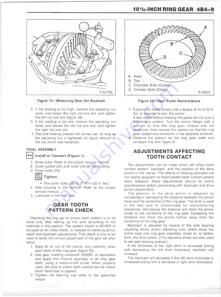
each tooth of the ring g e a r (figure 20).
2
. U se g ear m arking co m pond 1052351 or eq u ivalen t
and apply this m ixture sp aring ly to all ring g ear
teeth, using a m edium -stiff brush. W h e n properly
used, the area of pinion tooth contact will be visible
w hen hand load is applied.
3. T ig h te n th e b e a rin g c a p bolts to th e s p e c ifie d
torque.
4. E xp and th e brake shoes until a torque of 40 to 50 ft.
lbs. is required to turn the pinion.
A test m ade w ithout loading th e gears will not give a
satisfactory pattern. Turn the pinion flan g e with a
w re n c h so th a t th e rin g g e a r ro ta te s o n e full
revolution, th en reverse th e rotation so th at th e ring
g e a r rotates o ne revolution in the opposite direction.
5. O bserve th e pattern on th e ring g e a r teeth and
co m p are this with figure 21.
ADJUSTMENTS AFFECTING
TOOTH CONTACT
Two ad justm ents can be m a d e w hich will affect tooth
contact pattern: backlash , and the position of the drive
pinion in th e carrier. T h e effects of b earing prelo ad s are
not readily ap p are n t on hand loaded tooth contact pattern
tests; how ever, th e s e a d ju s tm e n ts sh o u ld be w ith in
specifications before p rec ee d in g with b acklash and drive
pinion adjustm ents.
T h e p o s itio n of th e d riv e p in io n is a d ju s te d by
increasing or d ecrea sin g th e d istan ce betw een the pinion
head and the cen te rlin e of the ring gear. T h e shim is used
in th e re a r a x le to c o m p e n s a te for m a n u fa c tu r in g
tolerances. D e creasin g the d istan ce will move the pinion
closer to th e cen terlin e of th e ring gear. Increasing th e
d is ta n c e will m ove the pinion fa rth e r aw a y from th e
cen terlin e of the ring gear.
B acklash is adjusted by m ean s of th e side b earing
adjusting shim s an d /o r adjusting nuts, w hich m ove th e
entire case and ring g e a r assem b ly closer to, or farth e r
from , the drive pinion. (T h e adjusting shim s are also used
to set side b earing p relo ad .)
If the th ickn ess of the right shim is increased (along
with d ecreasing th e left shim thickness), b acklash will
increase.
T h e b acklash will d e crea se if the left shim th ickn ess is
increased (along with a d ecrea se in right shim thickness).
Summary of Contents for 1989 Light Duty Truck
Page 1: ...vr V Light Duty Truck Unit Repair Manual...
Page 2: ......
Page 11: ...GENERAL INFORMATION OA 5 Figure 8 RV Models...
Page 13: ...GENERAL INFORMATION OA 7 Figure 11 ST Models...
Page 18: ......
Page 44: ......
Page 76: ...1B3 18 R 4 AIR CONDITIONING COMPRESSOR N...
Page 114: ......
Page 162: ......
Page 176: ...4B3 14 91 2 INCH RING GEAR...
Page 192: ...4B5 4 DANA REAR AXLES Figure 4 Spreading the Differential Case Figure 7 Removing the Ring Gear...
Page 218: ......
Page 220: ...4B6 2 12 INCH RING GEAR ROCKWELL F 04734 Figure 1 Rear Axle Components...
Page 229: ...12 INCH RING GEAR ROCKWELL 4B6 11 SPECIAL TOOLS Special Tools...
Page 230: ...4B6 12 12 INCH RING...
Page 240: ...4B7 10 LOCKING DIFFERENTIALS SPECIAL TOOLS Special Tools...
Page 260: ...4C2 6 93 4 INCH RING GEAR FRONT AXLE Figure 16 Removing the Pinion Inner Bearing...
Page 273: ...T TRUCK FRONT AXLE 4C3 3 F 05785 Figure 1 Axle Components...
Page 291: ...K TRUCK FRONT AXLE 4C4 3 Figure 1 Front Axle Com ponents K 15 25 Models...
Page 293: ...K TRUCK FRONT AXLE 4C4 5 Figure 3 Front Axle Com ponents K35 Models...
Page 318: ...C4 30 K TRUCK FBOHT AXLE...
Page 334: ......
Page 361: ...2 5 LITER L4 ENGINE 6A1 5 Figure 3 Cylinder Head Manifolds and Components...
Page 363: ...2 5 LITER L4 ENGINE 6A1 7 F 05715 Figure 5 Block and Components...
Page 395: ...2 8 LITER V 6 6A2 3 Figure 1 Engine Lubrication Diagram...
Page 396: ...6A2 4 2 8 LITER V 6 Figure 2 Engine Lubrication Diagram...
Page 424: ...6A2 32 2 8 LITER V 6...
Page 427: ...I 4 3 LITER V 6 6A3 3 Figure 1 Engine Lubrication Diagram B 07857...
Page 451: ...4 3 LITER V 6 6A3 27 SPECIFICATIONS ENGINE SPECIFICATIONS F 6344...
Page 457: ...4 8 LITER L6 6A4 3 Figure 2 Lubrication Diagram Front View...
Page 460: ...6A4 6 4 8 LITER L6 C 1 107 112 fK 108 3 109 165 129 B 05056 Figure 5 Block and Components...
Page 490: ...Ml...
Page 493: ...V8 ENGINE 6A5 3 Figure 1 Lubrication Diagram 5 0L and 5 7L Engines...
Page 494: ...6A5 4 V8 ENGINE Figure 2 Lubrication Diagram 5 0L and 5 7L Engines...
Page 530: ...6A5 40 V8 ENGINE Figure 81 Exhaust Manifold 7 4L Engines Figure 82 Water Pumps and Components...
Page 571: ...6 2 LITER DIESEL 6A7 35 Figure 58 Vacuum Pump Installed...
Page 576: ......
Page 582: ...6C1 6 MODEL 1MEF CARBURETOR Figure 9 Monojet Model 1MEF...
Page 604: ...6C2 6 MODEL M4MEF CARBURETOR Figure 9 Model M4MEF...
Page 640: ...6C4 8 MODEL 700 THROTTLE BODY...
Page 652: ...nmm...
Page 672: ......
Page 693: ...DISTRIBUTORS 6D5 13 Figure 27 Testing the Pickup Coil Figure 28 Testing the Ignition Coil...
Page 696: ......
Page 698: ...7A1 2 700 R4 AUTOMATIC TRANSMISSION Figure 1 Case and External Parts J H 0 0 5 3 7 0 0 R 4 R 2...
Page 745: ...700 R4 AUTOMATIC TRANSMISSION 7A1 49...
Page 762: ...7A2 2 400 475 AUTOMATIC TRANSMISSION Figure 1 Case and External Parts H H 0021 400 R 3...
Page 773: ...400 475 AUTOMATIC TRANSMISSION 7A2 13 Figure 29 Internal Parts H H 0 0 4 3 4 0 0 R 2...
Page 797: ...400 475 AUTOMATIC TRANSMISSION 7A2 37 Figure 93 Control Valve Assem bly...
Page 803: ...400 475 AUTOMATIC TRANSMISSION 7A2 43 Figure 104 Bushing Replacement Procedure...
Page 808: ...J c I i sal...
Page 838: ......
Page 840: ......
Page 842: ......
Page 850: ...7B1 12 HM 290 MANUAL TRANSMISSION J i t i a x V L...
Page 856: ...7B1 18 HM 290 MANUAL TRANSMISSION...
Page 892: ...7B1 54 HM 290 MANUAL TRANSMISSION Figure 93 Special Tools...
Page 897: ...HM 117 TRANSMISSION 7B2 5...
Page 901: ...HM 117 TRANSMISSION 7B2 9 B 05180 Figure 17 Installing the 1st and 2nd Synchronizer...
Page 912: ...20 HM...
Page 924: ...7B3 12 NEW PROCESS TRANSMISSION SPECIAL TOOLS...
Page 927: ...BORG WARNER TRANSMISSIONS 7B4 3 Figure 2 77 mm Transmission and Components...
Page 940: ...i ii iii m i in m i...
Page 944: ...7D1 4 TRANSFER CASE FO 5688 Figure 3 NP205 Transfer Case...
Page 952: ...7D1 12 TRANSFER CASE...
Page 963: ...NEW PROCESS 241 TRANSFER CASE 7D2 11 Figure 17 Oil Pump Pickup Screen Doweled Case Holes...
Page 964: ...7D2 12 NEW PROCESS 241 TRANSFER CASE Figure 18 NP 241 Transfer Case Cut Away...
Page 978: ......
Page 981: ...BORG WARNER 1370 TRANSFER CASE 7D4 3 J...
Page 992: ...7D4 14 BORG WARNER 1370 TRANSFER CASE Figure 26 Installing the Rear Output Yoke...
Page 993: ...BORG WARNER 1370 TRANSFER CASE 7D4 15 Figure 27 BW 1370 Transfer Case...
Page 997: ......
Page 998: ...X 8937...