


GENERATOR 6D2-7
Figure 13— Stator in the Slip Ring End Frame
4.
5.
6.
7.
8.
9.
10
.
11
.
• Make sure the side with the insulator material is
placed against the end fram e (ground).
Two screws and washers through the grounded heat
sink.
“ BAT” term inal nut (1) with the flat side down to the
insulated heat sink (figure 8).
If the brush holder, regulator, or connector has been
replaced, connect it by crim ping the connector(s) to
the other component(s). Then solder the connection
using as little heat as possible to avoid heat damage
to the regulator (figure 9).
Brush holder (131), regulator (226) and connector
assembly into the end fram e (figure 7).
• The metal side of the capacitor strap should rest
against the regulator connection.
One screw into the brush holder.
• If a brush holder with locator bosses is being
replaced with a holder w ithout locators, be sure
to align the brush holder assembly and hold it
w ith your fingers w hile tightening the brush
holder attaching screw.
Two insulated screws through the regulator connec
tor.
Brushes (130) into the brush holder (131).
• Retract the brushes in the h o ld e r.'
• Retain the retracted brushes with a toothpick or
retaining pin.
• Be sure th a t the pin or to o th p ic k e xte n d s
through the end fram e when the brush holder is
in place. After the rotor and drive end fram e are
installed, the pin or toothpick will be pulled out,
allowing the brushes to contact the slip rings.
Stator (220) into the end frame, aligning the three
stator leads to the three rectifier bridge term inals
(figure 14).
Three terminal nuts. Tighten the nuts securely.
DRIVE END FRAME
■+4- Install or Connect (Figures 4 and 15)
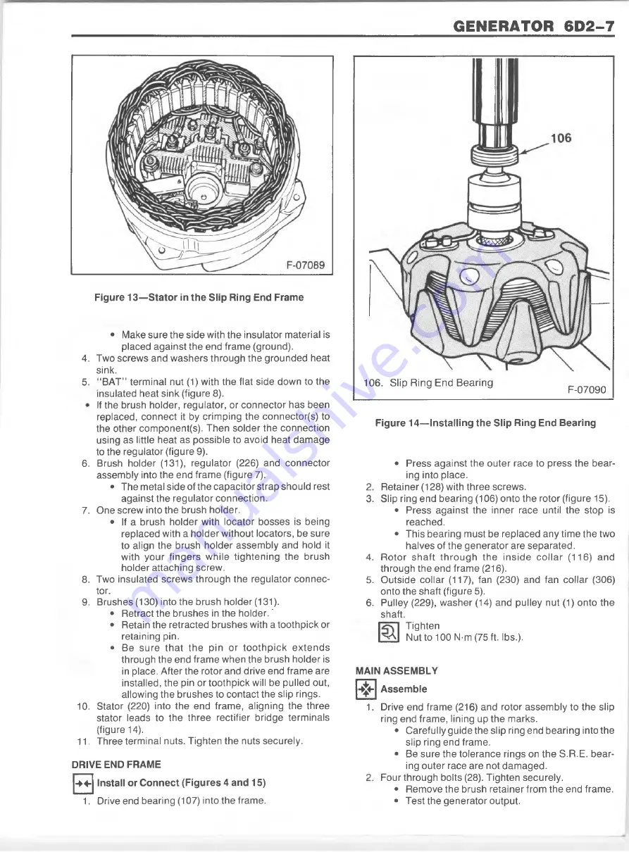
Figure 14— Installing the Slip Ring End Bearing
2
.
3.
4.
5.
6
.
• Press against the outer race to press the bear
ing into place.
Retainer (128) with three screws.
Slip ring end bearing (106) onto the rotor (figure 15).
• Press against the inner race until the stop is
reached.
• This bearing must be replaced any tim e the two
halves of the generator are separated.
R otor sh a ft th ro u g h th e inside c o lla r (116) and
through the end fram e (216).
Outside collar (117), fan (230) and fan collar (306)
onto the shaft (figure 5).
Pulley (229), washer (14) and pulley nut (1) onto the
shaft.
Tighten
> A I Nut to 100 N-m (75 ft. lbs.).
MAIN ASSEMBLY
*
1
.
1. Drive end bearing (107) into the frame.
Assemble
Drive end frame (216) and rotor assembly to the slip
ring end frame, lining up the marks.
• Carefully guide the slip ring end bearing into the
slip ring end frame.
• Be sure the tolerance rings on the S.R.E. bear
ing outer race are not dam aged.
Four through bolts (28). Tighten securely.
• Remove the brush retainer from the end frame.
• Test the generator output.
F-07090
106. Slip R ing End B earing
Summary of Contents for 1989 Light Duty Truck
Page 1: ...vr V Light Duty Truck Unit Repair Manual...
Page 2: ......
Page 11: ...GENERAL INFORMATION OA 5 Figure 8 RV Models...
Page 13: ...GENERAL INFORMATION OA 7 Figure 11 ST Models...
Page 18: ......
Page 44: ......
Page 76: ...1B3 18 R 4 AIR CONDITIONING COMPRESSOR N...
Page 114: ......
Page 162: ......
Page 176: ...4B3 14 91 2 INCH RING GEAR...
Page 192: ...4B5 4 DANA REAR AXLES Figure 4 Spreading the Differential Case Figure 7 Removing the Ring Gear...
Page 218: ......
Page 220: ...4B6 2 12 INCH RING GEAR ROCKWELL F 04734 Figure 1 Rear Axle Components...
Page 229: ...12 INCH RING GEAR ROCKWELL 4B6 11 SPECIAL TOOLS Special Tools...
Page 230: ...4B6 12 12 INCH RING...
Page 240: ...4B7 10 LOCKING DIFFERENTIALS SPECIAL TOOLS Special Tools...
Page 260: ...4C2 6 93 4 INCH RING GEAR FRONT AXLE Figure 16 Removing the Pinion Inner Bearing...
Page 273: ...T TRUCK FRONT AXLE 4C3 3 F 05785 Figure 1 Axle Components...
Page 291: ...K TRUCK FRONT AXLE 4C4 3 Figure 1 Front Axle Com ponents K 15 25 Models...
Page 293: ...K TRUCK FRONT AXLE 4C4 5 Figure 3 Front Axle Com ponents K35 Models...
Page 318: ...C4 30 K TRUCK FBOHT AXLE...
Page 334: ......
Page 361: ...2 5 LITER L4 ENGINE 6A1 5 Figure 3 Cylinder Head Manifolds and Components...
Page 363: ...2 5 LITER L4 ENGINE 6A1 7 F 05715 Figure 5 Block and Components...
Page 395: ...2 8 LITER V 6 6A2 3 Figure 1 Engine Lubrication Diagram...
Page 396: ...6A2 4 2 8 LITER V 6 Figure 2 Engine Lubrication Diagram...
Page 424: ...6A2 32 2 8 LITER V 6...
Page 427: ...I 4 3 LITER V 6 6A3 3 Figure 1 Engine Lubrication Diagram B 07857...
Page 451: ...4 3 LITER V 6 6A3 27 SPECIFICATIONS ENGINE SPECIFICATIONS F 6344...
Page 457: ...4 8 LITER L6 6A4 3 Figure 2 Lubrication Diagram Front View...
Page 460: ...6A4 6 4 8 LITER L6 C 1 107 112 fK 108 3 109 165 129 B 05056 Figure 5 Block and Components...
Page 490: ...Ml...
Page 493: ...V8 ENGINE 6A5 3 Figure 1 Lubrication Diagram 5 0L and 5 7L Engines...
Page 494: ...6A5 4 V8 ENGINE Figure 2 Lubrication Diagram 5 0L and 5 7L Engines...
Page 530: ...6A5 40 V8 ENGINE Figure 81 Exhaust Manifold 7 4L Engines Figure 82 Water Pumps and Components...
Page 571: ...6 2 LITER DIESEL 6A7 35 Figure 58 Vacuum Pump Installed...
Page 576: ......
Page 582: ...6C1 6 MODEL 1MEF CARBURETOR Figure 9 Monojet Model 1MEF...
Page 604: ...6C2 6 MODEL M4MEF CARBURETOR Figure 9 Model M4MEF...
Page 640: ...6C4 8 MODEL 700 THROTTLE BODY...
Page 652: ...nmm...
Page 672: ......
Page 693: ...DISTRIBUTORS 6D5 13 Figure 27 Testing the Pickup Coil Figure 28 Testing the Ignition Coil...
Page 696: ......
Page 698: ...7A1 2 700 R4 AUTOMATIC TRANSMISSION Figure 1 Case and External Parts J H 0 0 5 3 7 0 0 R 4 R 2...
Page 745: ...700 R4 AUTOMATIC TRANSMISSION 7A1 49...
Page 762: ...7A2 2 400 475 AUTOMATIC TRANSMISSION Figure 1 Case and External Parts H H 0021 400 R 3...
Page 773: ...400 475 AUTOMATIC TRANSMISSION 7A2 13 Figure 29 Internal Parts H H 0 0 4 3 4 0 0 R 2...
Page 797: ...400 475 AUTOMATIC TRANSMISSION 7A2 37 Figure 93 Control Valve Assem bly...
Page 803: ...400 475 AUTOMATIC TRANSMISSION 7A2 43 Figure 104 Bushing Replacement Procedure...
Page 808: ...J c I i sal...
Page 838: ......
Page 840: ......
Page 842: ......
Page 850: ...7B1 12 HM 290 MANUAL TRANSMISSION J i t i a x V L...
Page 856: ...7B1 18 HM 290 MANUAL TRANSMISSION...
Page 892: ...7B1 54 HM 290 MANUAL TRANSMISSION Figure 93 Special Tools...
Page 897: ...HM 117 TRANSMISSION 7B2 5...
Page 901: ...HM 117 TRANSMISSION 7B2 9 B 05180 Figure 17 Installing the 1st and 2nd Synchronizer...
Page 912: ...20 HM...
Page 924: ...7B3 12 NEW PROCESS TRANSMISSION SPECIAL TOOLS...
Page 927: ...BORG WARNER TRANSMISSIONS 7B4 3 Figure 2 77 mm Transmission and Components...
Page 940: ...i ii iii m i in m i...
Page 944: ...7D1 4 TRANSFER CASE FO 5688 Figure 3 NP205 Transfer Case...
Page 952: ...7D1 12 TRANSFER CASE...
Page 963: ...NEW PROCESS 241 TRANSFER CASE 7D2 11 Figure 17 Oil Pump Pickup Screen Doweled Case Holes...
Page 964: ...7D2 12 NEW PROCESS 241 TRANSFER CASE Figure 18 NP 241 Transfer Case Cut Away...
Page 978: ......
Page 981: ...BORG WARNER 1370 TRANSFER CASE 7D4 3 J...
Page 992: ...7D4 14 BORG WARNER 1370 TRANSFER CASE Figure 26 Installing the Rear Output Yoke...
Page 993: ...BORG WARNER 1370 TRANSFER CASE 7D4 15 Figure 27 BW 1370 Transfer Case...
Page 997: ......
Page 998: ...X 8937...