


GE Multilin
T60 Transformer Protection System
C-19
APPENDIX C
C.5 IEC 61850 IMPLEMENTATION VIA ENERVISTA UR SETUP
C
•
Header.
•
Substation.
•
Communication.
•
IED section (one or more).
•
DataTypeTemplates.
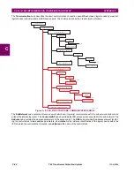
The root file structure of an SCD file is illustrated below.
Figure C–6: SCD FILE STRUCTURE, SCL (ROOT) NODE
Like ICD files, the
Header
node identifies the SCD file and its version, and specifies options for the mapping of names to
signals.
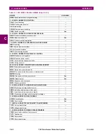
The
Substation
node describes the substation parameters:
Figure C–7: SCD FILE STRUCTURE, SUBSTATION NODE
842791A1.CDR
SCL
Header (id, version, revision, toolID, nameStructure)
IED Section (IED 2)
Communication
IED Section (IED 1)
Substation
Other IED Sections
DataTypeTemplates
842792A1.CDR
Substation
EquipmentContainer
VoltageLevel
Function
PowerSystemResource
Power Transformer
GeneralEquipment
EquipmentContainer
Bay
Voltage
PowerSystemResource
SubFunction
GeneralEquipment
Summary of Contents for UR T60
Page 10: ...x T60 Transformer Protection System GE Multilin TABLE OF CONTENTS ...
Page 14: ...xiv T60 Transformer Protection System GE Multilin 0 1 BATTERY DISPOSAL 0 BATTERY DISPOSAL 0 ...
Page 34: ...1 20 T60 Transformer Protection System GE Multilin 1 5 USING THE RELAY 1 GETTING STARTED 1 ...
Page 436: ...5 298 T60 Transformer Protection System GE Multilin 5 10 TESTING 5 SETTINGS 5 ...
Page 678: ...C 30 T60 Transformer Protection System GE Multilin C 7 LOGICAL NODES APPENDIX C C ...
Page 688: ...D 10 T60 Transformer Protection System GE Multilin D 1 IEC 60870 5 104 PROTOCOL APPENDIX D D ...
Page 700: ...E 12 T60 Transformer Protection System GE Multilin E 2 DNP POINT LISTS APPENDIX E E ...


