


5-80
T60 Transformer Protection System
GE Multilin
5.4 SYSTEM SETUP
5 SETTINGS
5
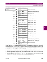
The loss of life function calculates the insulation aging acceleration factor using the settings entered in this section, by
following equation:
(EQ 5.8)
where
is the rated hottest-spot temperature as per the table below,
and
is the actual computed winding hottest-spot temperature.
The aging acceleration factor is computed every minute. It has a value of 1.0 when the actual winding hottest spot tem-
perature is equal to the rated temperature, is greater than 1 if the actual temperature is above the rated temperature,
and less than 1 if the actual temperature is below the rated temperature.
•
NO LOAD LOSS
: This setting is obtained from the transformer data and is used to calculate the aging acceleration
factor.
•
TYPE OF COOLING
: The setting defines the type of transformer cooling and is used to calculate the aging accelera-
tion factor. The values and their description for this setting are as follows:
“OA”: oil-air
“FA”: forced air
“Non-directed FOA/FOW”: non-directed forced-oil-air/forced-oil-water
“Directed FOA/FOW”: directed forced-oil-air/forced-oil-water
“Sealed Self Cooled”, “Vented Self Cooled”, “Forced Cooled”: as named
•
TOP OIL RISE OVER AMBIENT
: This setting should be available from the transformer nameplate data
•
THERMAL CAPACITY
: The setting should be available from the transformer nameplate data. If not, refer to the follow-
ing calculations. For the “OA” and “FA” cooling types:
C = 0.06 (core and coil assembly in lbs.) + 0.04 (tank and fittings in lbs.) +1.33 (gallons of oil), Wh/°C; or
C = 0.0272 (core and coil assembly in kg) + 0.01814 (tank and fittings in kg) + 5.034 (L of oil), Wh/°C
For the “Non-directed FOA/FOW” (non-directed forced-oil-air/forced-oil-water) or “Directed FOA/FOW” (directed
forced-oil-air/forced-oil-water) cooling types, the thermal capacity is given by:
C = 0.06 (core and coil assembly in lbs.) + 0.06 (tank and fittings in lbs.) + 1.93 (gallons of oil), Wh/°C; or
C =0.0272 (weight of core and coil assembly in kg) + 0.0272 (weight of tank and fittings in kg) + 7.305 (L of oil), Wh/°C
For dry-type power transformers:
C = 0.048
×
(weight of copper winding); or
C = 0.015
×
(weight of core and copper windings from the nameplate); or
C = 0.12
×
(weight of aluminum windings); or
C = 0.02
×
(weight of core and aluminum coils from the nameplate)
•
WINDING THERMAL TIME CONSTANT
: Required for insulation aging calculation. If this value is not available from
the transformer data, select “2 min.”.
RATED WINDING
TEMPERATURE
POWER
CAPACITY
NORMAL LIFE
EXPECTANCY
AT
Θ
H_R
Oil
55°C
≤
500 kVA
180000 hrs
95°C
≤
100 MVA
6.5
×
10
4
hrs
95°C
65°C
≤
500 kVA
20 years
110°C
≤
100 MVA
6.5
×
10
4
hrs
110°C
> 100 MVA
6.5
×
10
4
hrs
110°C
Dry
80°C
Any
20 years
140°C
115°C
Any
20 years
175°C
150°C
Any
20 years
210°C
F
AA
t
( )
e
15000
Θ
H
_
R
273
+
-----------------------------
15000
Θ
H t
( )
273
+
----------------------------
–
=
Θ
H
_
R
Θ
H t
( )
Summary of Contents for UR T60
Page 10: ...x T60 Transformer Protection System GE Multilin TABLE OF CONTENTS ...
Page 14: ...xiv T60 Transformer Protection System GE Multilin 0 1 BATTERY DISPOSAL 0 BATTERY DISPOSAL 0 ...
Page 34: ...1 20 T60 Transformer Protection System GE Multilin 1 5 USING THE RELAY 1 GETTING STARTED 1 ...
Page 436: ...5 298 T60 Transformer Protection System GE Multilin 5 10 TESTING 5 SETTINGS 5 ...
Page 678: ...C 30 T60 Transformer Protection System GE Multilin C 7 LOGICAL NODES APPENDIX C C ...
Page 688: ...D 10 T60 Transformer Protection System GE Multilin D 1 IEC 60870 5 104 PROTOCOL APPENDIX D D ...
Page 700: ...E 12 T60 Transformer Protection System GE Multilin E 2 DNP POINT LISTS APPENDIX E E ...


