


GE Multilin
T60 Transformer Protection System
5-279
5 SETTINGS
5.8 INPUTS AND OUTPUTS
5
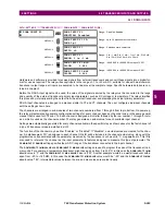
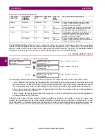
Setting the
TELEPROT INPUT ~~ DEFAULT
setting to “On” defaults the input to logic 1 when the channel fails. A value of “Off”
defaults the input to logic 0 when the channel fails.
The “Latest/On” and “Latest/Off” values freeze the input in case of lost communications. If the latest state is not known,
such as after relay power-up but before the first communication exchange, then the input defaults to logic 1 for “Latest/On”
and logic 0 for “Latest/Off”.
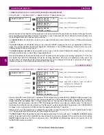
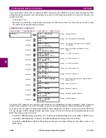
c) TELEPROTECTION OUTPUTS
PATH: SETTINGS
INPUTS/OUTPUTS
TELEPROTECTION
TELEPROT OUTPUTS
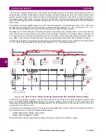
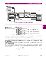
As the following figure demonstrates, processing of the teleprotection inputs/outputs is dependent on the number of com-
munication channels and terminals. On two-terminal two-channel systems, they are processed continuously on each chan-
nel and mapped separately per channel. Therefore, to achieve redundancy, the user must assign the same operand on
both channels (teleprotection outputs at the sending end or corresponding teleprotection inputs at the receiving end). On
three-terminal two-channel systems, redundancy is achieved by programming signal re-transmittal in the case of channel
failure between any pair of relays.
TELEPROT OUTPUTS
TELEPROT OUTPUT 1-1:
Off
Range: FlexLogic™ operand
MESSAGE
TELEPROT OUTPUT 1-2:
Off
Range: FlexLogic™ operand
↓
MESSAGE
TELEPROT OUTPUT 1-16:
Off
Range: FlexLogic™ operand
MESSAGE
TELEPROT OUTPUT 2-1:
Off
Range: FlexLogic™ operand
MESSAGE
TELEPROT OUTPUT 2-2:
Off
Range: FlexLogic™ operand
↓
MESSAGE
TELEPROT OUTPUT 2-16:
Off
Range: FlexLogic™ operand
Summary of Contents for UR T60
Page 10: ...x T60 Transformer Protection System GE Multilin TABLE OF CONTENTS ...
Page 14: ...xiv T60 Transformer Protection System GE Multilin 0 1 BATTERY DISPOSAL 0 BATTERY DISPOSAL 0 ...
Page 34: ...1 20 T60 Transformer Protection System GE Multilin 1 5 USING THE RELAY 1 GETTING STARTED 1 ...
Page 436: ...5 298 T60 Transformer Protection System GE Multilin 5 10 TESTING 5 SETTINGS 5 ...
Page 678: ...C 30 T60 Transformer Protection System GE Multilin C 7 LOGICAL NODES APPENDIX C C ...
Page 688: ...D 10 T60 Transformer Protection System GE Multilin D 1 IEC 60870 5 104 PROTOCOL APPENDIX D D ...
Page 700: ...E 12 T60 Transformer Protection System GE Multilin E 2 DNP POINT LISTS APPENDIX E E ...


