


GE Multilin
T60 Transformer Protection System
1-17
1 GETTING STARTED
1.5 USING THE RELAY
1
1.5USING THE RELAY
1.5.1 FACEPLATE KEYPAD
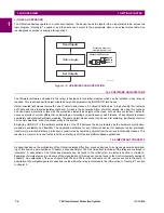
Display messages are organized into pages under the following headings: actual values, settings, commands, and targets.
The MENU key navigates through these pages. Each heading page is broken down further into logical subgroups.
The MESSAGE keys navigate through the subgroups. The VALUE keys scroll increment or decrement numerical setting
values when in programming mode. These keys also scroll through alphanumeric values in the text edit mode. Alterna-
tively, values may also be entered with the numeric keypad.
The decimal key initiates and advance to the next character in text edit mode or enters a decimal point. The HELP key may
be pressed at any time for context sensitive help messages. The ENTER key stores altered setting values.
1.5.2 MENU NAVIGATION
Press the MENU key to select the desired header display page (top-level menu). The header title appears momentarily fol-
lowed by a header display page menu item. Each press of the MENU key advances through the following main heading
pages:
•
Actual values.
•
Settings.
•
Commands.
•
Targets.
•
User displays (when enabled).
1.5.3 MENU HIERARCHY
The setting and actual value messages are arranged hierarchically. The header display pages are indicated by double
scroll bar characters (
), while sub-header pages are indicated by single scroll bar characters (
). The header display
pages represent the highest level of the hierarchy and the sub-header display pages fall below this level. The MESSAGE
UP and DOWN keys move within a group of headers, sub-headers, setting values, or actual values. Continually pressing
the MESSAGE RIGHT key from a header display displays specific information for the header category. Conversely, contin-
ually pressing the MESSAGE LEFT key from a setting value or actual value display returns to the header display.
1.5.4 RELAY ACTIVATION
The relay is defaulted to the “Not Programmed” state when it leaves the factory. This safeguards against the installation of
a relay whose settings have not been entered. When powered up successfully, the Trouble LED will be on and the In Ser-
vice LED off. The relay in the “Not Programmed” state will block signaling of any output relay. These conditions will remain
until the relay is explicitly put in the “Programmed” state.
Select the menu message
SETTINGS
PRODUCT SETUP
INSTALLATION
RELAY SETTINGS
HIGHEST LEVEL
LOWEST LEVEL (SETTING VALUE)
SETTINGS
PRODUCT SETUP
SECURITY
ACCESS LEVEL:
Restricted
SETTINGS
SYSTEM SETUP
RELAY SETTINGS:
Not Programmed
Summary of Contents for UR T60
Page 10: ...x T60 Transformer Protection System GE Multilin TABLE OF CONTENTS ...
Page 14: ...xiv T60 Transformer Protection System GE Multilin 0 1 BATTERY DISPOSAL 0 BATTERY DISPOSAL 0 ...
Page 34: ...1 20 T60 Transformer Protection System GE Multilin 1 5 USING THE RELAY 1 GETTING STARTED 1 ...
Page 436: ...5 298 T60 Transformer Protection System GE Multilin 5 10 TESTING 5 SETTINGS 5 ...
Page 678: ...C 30 T60 Transformer Protection System GE Multilin C 7 LOGICAL NODES APPENDIX C C ...
Page 688: ...D 10 T60 Transformer Protection System GE Multilin D 1 IEC 60870 5 104 PROTOCOL APPENDIX D D ...
Page 700: ...E 12 T60 Transformer Protection System GE Multilin E 2 DNP POINT LISTS APPENDIX E E ...


