


5-226
T60 Transformer Protection System
GE Multilin
5.6 GROUPED ELEMENTS
5 SETTINGS
5
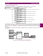
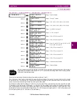
INVERSE CURVE B:
The curve for the Volts/Hertz Inverse Curve B shape is derived from the formula:
(EQ 5.46)
where:
T
= Operating Time
TDM
= Time Delay Multiplier (delay in sec.)
V
= fundamental RMS value of voltage (pu)
F
= frequency of voltage signal (pu)
Pickup
= volts-per-hertz pickup setpoint (pu)
The volts/hertz inverse B curves are shown below.
Figure 5–124: VOLTS-PER-HERTZ CURVES, INVERSE CURVE B
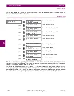
INVERSE CURVE C:
The curve for the Volts/Hertz Inverse Curve C shape is derived from the formula:
(EQ 5.47)
where:
T
= Operating Time
TDM
= Time Delay Multiplier (delay in sec.)
V
= fundamental RMS value of voltage (pu)
F
= frequency of voltage signal (pu)
Pickup
= volts-per-hertz pickup setpoint (pu)
T
TDM
V
F
----
Pickup
⁄
1
–
----------------------------------------------
when
V
F
----
Pickup
>
=
Ti
me
to
trip
(in
seconds)
Multiples of volts per hertz pickup
830739A1.CDR
Time
delay
setting
T
TDM
V
F
----
Pickup
⁄
0.5
1
–
-----------------------------------------------------
when
V
F
----
Pickup
>
=
Summary of Contents for UR T60
Page 10: ...x T60 Transformer Protection System GE Multilin TABLE OF CONTENTS ...
Page 14: ...xiv T60 Transformer Protection System GE Multilin 0 1 BATTERY DISPOSAL 0 BATTERY DISPOSAL 0 ...
Page 34: ...1 20 T60 Transformer Protection System GE Multilin 1 5 USING THE RELAY 1 GETTING STARTED 1 ...
Page 436: ...5 298 T60 Transformer Protection System GE Multilin 5 10 TESTING 5 SETTINGS 5 ...
Page 678: ...C 30 T60 Transformer Protection System GE Multilin C 7 LOGICAL NODES APPENDIX C C ...
Page 688: ...D 10 T60 Transformer Protection System GE Multilin D 1 IEC 60870 5 104 PROTOCOL APPENDIX D D ...
Page 700: ...E 12 T60 Transformer Protection System GE Multilin E 2 DNP POINT LISTS APPENDIX E E ...


