


GE Multilin
T60 Transformer Protection System
5-105
5 SETTINGS
5.4 SYSTEM SETUP
5
5.4.8 PHASOR MEASUREMENT UNIT
a) MAIN MENU
PATH: SETTINGS
SYSTEM SETUP
PHASOR MEASUREMENT UNIT
The T60 Transformer Protection System is provided with an optional phasor measurement unit feature.
This feature is specified as a software option at the time of ordering. The number of phasor measurement
units available is also dependent on this option. Refer to the
Ordering
section of chapter 2 for additional
details.
The
PHASOR MEASUREMENT UNIT
menu allows specifying basic parameters of the measurements process such as signal
source, ID and station name, calibration data, triggering, recording, and content for transmission on each of the supported
ports. The reporting ports menus allow specifying the content and rate of reporting on each of the supported ports.
Precise IRIG-B input is vital for correct synchrophasor measurement and reporting. A DC level shift IRIG-B receiver
must
be used for the phasor measurement unit to output proper synchrophasor values.
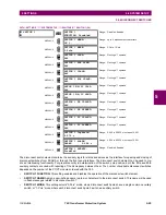
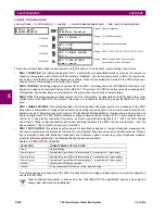
The PMU settings are organized in logical groups as follows.
PATH: SETTINGS
SYSTEM SETUP
PHASOR MEASUREMENT UNIT
PHASOR MEASUREMENT UNIT 1
PHASOR MEASUREMENT
UNIT
PHASOR MEASUREMENT
UNIT 1
See below.
MESSAGE
REPORTING OVER
NETWORK
PHASOR MEASUREMENT
UNIT 1
PMU 1 BASIC
CONFIGURATION
MESSAGE
PMU 1
CALIBRATION
MESSAGE
PMU 1
COMMUNICATION
MESSAGE
PMU 1
TRIGGERING
MESSAGE
PMU 1
RECORDING
NOTE
Summary of Contents for UR T60
Page 10: ...x T60 Transformer Protection System GE Multilin TABLE OF CONTENTS ...
Page 14: ...xiv T60 Transformer Protection System GE Multilin 0 1 BATTERY DISPOSAL 0 BATTERY DISPOSAL 0 ...
Page 34: ...1 20 T60 Transformer Protection System GE Multilin 1 5 USING THE RELAY 1 GETTING STARTED 1 ...
Page 436: ...5 298 T60 Transformer Protection System GE Multilin 5 10 TESTING 5 SETTINGS 5 ...
Page 678: ...C 30 T60 Transformer Protection System GE Multilin C 7 LOGICAL NODES APPENDIX C C ...
Page 688: ...D 10 T60 Transformer Protection System GE Multilin D 1 IEC 60870 5 104 PROTOCOL APPENDIX D D ...
Page 700: ...E 12 T60 Transformer Protection System GE Multilin E 2 DNP POINT LISTS APPENDIX E E ...


