


GE Multilin
T60 Transformer Protection System
5-175
5 SETTINGS
5.6 GROUPED ELEMENTS
5
Figure 5–88: PERCENT DIFFERENTIAL CALCULATIONS
The T60 percent differential element is based on a configurable dual-breakpoint / dual-slope differential restraint character-
istic. The purpose of the preset characteristic is to define the differential restraint ratio for the transformer winding currents
at different loading conditions and distinguish between external and internal faults. Differential restraint ratio variations
occur due to current unbalance between primary and secondary windings and can be caused by the following:
1.
Inherent CT inaccuracies.
2.
Onload tap changer operation: it adjusts the transformer ratio and consequently the winding currents.
3.
CT saturation.
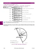
Figure 5–89: PERCENT DIFFERENTIAL OPERATING CHARACTERISTIC
...
∑
Winding 1
current
waveform
Winding 2
current
waveform
Winding ‘n’
current
waveform
Magnitude
phase angle, and
zero sequence
compensation
(as required)
Magnitude
phase angle, and
zero sequence
compensation
(as required)
Magnitude
phase angle, and
zero sequence
compensation
(as required)
Decaying dc
offset filter
Decaying dc
offset filter
Decaying dc
offset filter
Discrete Fourier
Transform
MAX
Differential
phasor
Discrete Fourier
Transform
Discrete Fourier
Transform
Restraint
phasor
828714A1.CDR
Transition region
(cubic spline)
Breakpoint 2
Breakpoint 1
Id
(Ir)
Pickup
Slope 2
region
Ir
0
2
4
6
8
10
2
4
6
8
10
828750A1.CDR
Summary of Contents for UR T60
Page 10: ...x T60 Transformer Protection System GE Multilin TABLE OF CONTENTS ...
Page 14: ...xiv T60 Transformer Protection System GE Multilin 0 1 BATTERY DISPOSAL 0 BATTERY DISPOSAL 0 ...
Page 34: ...1 20 T60 Transformer Protection System GE Multilin 1 5 USING THE RELAY 1 GETTING STARTED 1 ...
Page 436: ...5 298 T60 Transformer Protection System GE Multilin 5 10 TESTING 5 SETTINGS 5 ...
Page 678: ...C 30 T60 Transformer Protection System GE Multilin C 7 LOGICAL NODES APPENDIX C C ...
Page 688: ...D 10 T60 Transformer Protection System GE Multilin D 1 IEC 60870 5 104 PROTOCOL APPENDIX D D ...
Page 700: ...E 12 T60 Transformer Protection System GE Multilin E 2 DNP POINT LISTS APPENDIX E E ...


