


GE Multilin
T60 Transformer Protection System
5-95
5 SETTINGS
5.4 SYSTEM SETUP
5
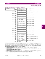
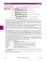
5.4.6 DISCONNECT SWITCHES
PATH: SETTINGS
SYSTEM SETUP
SWITCHES
SWITCH 1(24)
The disconnect switch element contains the auxiliary logic for status and serves as the interface for opening and closing of
disconnect switches from SCADA or through the front panel interface. The disconnect switch element can be used to cre-
ate an interlocking functionality. For greater security in determination of the switch pole position, both the 89/a and 89/b
auxiliary contacts are used with reporting of the discrepancy between them. The number of available disconnect switches
depends on the number of the CT/VT modules ordered with the T60.
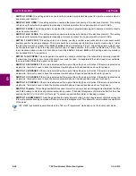
•
SWITCH 1 FUNCTION:
This setting enables and disables the operation of the disconnect switch element.
•
SWITCH 1 NAME:
Assign a user-defined name (up to six characters) to the disconnect switch. This name will be used
in flash messages related to disconnect switch 1.
•
SWITCH 1 MODE:
This setting selects “3-Pole” mode, where disconnect switch poles have a single common auxiliary
switch, or “1-Pole” mode where each disconnect switch pole has its own auxiliary switch.
SWITCH 1
SWITCH 1
FUNCTION: Disabled
Range: Disabled, Enabled
MESSAGE
SWITCH 1 NAME:
SW 1
Range: up to 6 alphanumeric characters
MESSAGE
SWITCH 1 MODE:
3-Pole
Range: 3-Pole, 1-Pole
MESSAGE
SWITCH 1 OPEN:
Off
Range: FlexLogic™ operand
MESSAGE
SWITCH 1 BLK OPEN:
Off
Range: FlexLogic™ operand
MESSAGE
SWITCH 1 CLOSE:
Off
Range: FlexLogic™ operand
MESSAGE
SWITCH 1 BLK CLOSE:
Off
Range: FlexLogic™ operand
MESSAGE
SWTCH 1
Φ
A/3P CLSD:
Off
Range: FlexLogic™ operand
MESSAGE
SWTCH 1
Φ
A/3P OPND:
Off
Range: FlexLogic™ operand
MESSAGE
SWITCH 1
Φ
B CLOSED:
Off
Range: FlexLogic™ operand
MESSAGE
SWITCH 1
Φ
B OPENED:
Off
Range: FlexLogic™ operand
MESSAGE
SWITCH 1
Φ
C CLOSED:
Off
Range: FlexLogic™ operand
MESSAGE
SWITCH 1
Φ
C OPENED:
Off
Range: FlexLogic™ operand
MESSAGE
SWITCH 1 Toperate:
0.070 s
Range: 0.000 to 65.535 s in steps of 0.001
MESSAGE
SWITCH 1 ALARM
DELAY: 0.000
s
Range: 0.000 to 65.535 s in steps of 0.001
MESSAGE
SWITCH 1 EVENTS:
Disabled
Range: Disabled, Enabled
Summary of Contents for UR T60
Page 10: ...x T60 Transformer Protection System GE Multilin TABLE OF CONTENTS ...
Page 14: ...xiv T60 Transformer Protection System GE Multilin 0 1 BATTERY DISPOSAL 0 BATTERY DISPOSAL 0 ...
Page 34: ...1 20 T60 Transformer Protection System GE Multilin 1 5 USING THE RELAY 1 GETTING STARTED 1 ...
Page 436: ...5 298 T60 Transformer Protection System GE Multilin 5 10 TESTING 5 SETTINGS 5 ...
Page 678: ...C 30 T60 Transformer Protection System GE Multilin C 7 LOGICAL NODES APPENDIX C C ...
Page 688: ...D 10 T60 Transformer Protection System GE Multilin D 1 IEC 60870 5 104 PROTOCOL APPENDIX D D ...
Page 700: ...E 12 T60 Transformer Protection System GE Multilin E 2 DNP POINT LISTS APPENDIX E E ...


