


4-20
T60 Transformer Protection System
GE Multilin
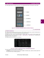
4.3 FACEPLATE INTERFACE
4 HUMAN INTERFACES
4
2.
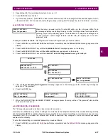
Bend the tab at the center of the tool tail as shown below.
The following procedure describes how to remove the LED labels from the T60 enhanced front panel and insert the custom
labels.
1.
Use the knife to lift the LED label and slide the label tool underneath. Make sure the bent tabs are pointing away from
the relay.
2.
Slide the label tool under the LED label until the tabs snap out as shown below. This will attach the label tool to the LED
label.
Summary of Contents for UR T60
Page 10: ...x T60 Transformer Protection System GE Multilin TABLE OF CONTENTS ...
Page 14: ...xiv T60 Transformer Protection System GE Multilin 0 1 BATTERY DISPOSAL 0 BATTERY DISPOSAL 0 ...
Page 34: ...1 20 T60 Transformer Protection System GE Multilin 1 5 USING THE RELAY 1 GETTING STARTED 1 ...
Page 436: ...5 298 T60 Transformer Protection System GE Multilin 5 10 TESTING 5 SETTINGS 5 ...
Page 678: ...C 30 T60 Transformer Protection System GE Multilin C 7 LOGICAL NODES APPENDIX C C ...
Page 688: ...D 10 T60 Transformer Protection System GE Multilin D 1 IEC 60870 5 104 PROTOCOL APPENDIX D D ...
Page 700: ...E 12 T60 Transformer Protection System GE Multilin E 2 DNP POINT LISTS APPENDIX E E ...


