


5-258
T60 Transformer Protection System
GE Multilin
5.7 CONTROL ELEMENTS
5 SETTINGS
5
e) VT FUSE FAILURE
PATH: SETTINGS
CONTROL ELEMENTS
MONITORING ELEMENTS
VT FUSE FAILURE 1(6)
Every signal source includes a fuse failure scheme.
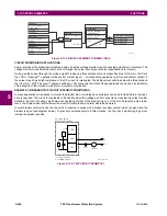
The VT fuse failure detector can be used to raise an alarm and/or block elements that may operate incorrectly for a full or
partial loss of AC potential caused by one or more blown fuses. Some elements that might be blocked (via the
BLOCK
input)
are distance, voltage restrained overcurrent, and directional current.
There are two classes of fuse failure that may occur:
•
Class A: loss of one or two phases.
•
Class B: loss of all three phases.
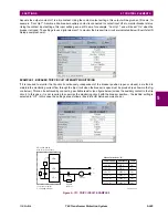
Different means of detection are required for each class. An indication of class A failures is a significant level of negative-
sequence voltage, whereas an indication of class B failures is when positive sequence current is present and there is an
insignificant amount of positive sequence voltage. These noted indications of fuse failure could also be present when faults
are present on the system, so a means of detecting faults and inhibiting fuse failure declarations during these events is pro-
vided. Once the fuse failure condition is declared, it will be sealed-in until the cause that generated it disappears.
An additional condition is introduced to inhibit a fuse failure declaration when the monitored circuit is de-energized; positive-
sequence voltage and current are both below threshold levels.
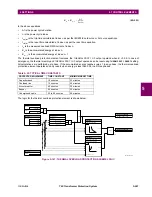
The function setting enables and disables the fuse failure feature for each source.
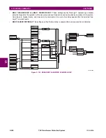
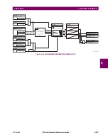
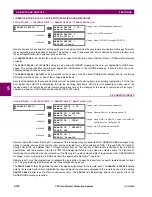
Figure 5–145: VT FUSE FAIL SCHEME LOGIC
VT FUSE FAILURE 1
VT FUSE FAILURE 1
FUNCTION: Disabled
Range: Disabled, Enabled
$0&'5
)86(
)$,/
)$8/7
$1'
$1'
$1'
$1'
6(7
5(6(7
5HVHWGRPLQDQW
/DWFK
$1'
$1'
$1'
$1'
$1'
25
25
25
25
/DWFK
6(7
5HVHWGRPLQDQW
5(6(7
)XQFWLRQ
6(77,1*
'LVDEOHG
(QDEOHG
6285&(
9B
9B
,B
&203$5$7256
5XQ
9BSX
5XQ
9B!SX
5XQ
,B!SX
5XQ
9BSX
5XQ
,BSX
65&''23
)/(;/2*,&23(5$1'6
F\FOHV
F\FOHV
65&97)86()$,/23
)/(;/2*,&23(5$1'6
65&97)86()$,/'32
65&97)86()$,/92//266
)/(;/2*,&23(5$1'
7,0(5
23(132/(23
7KH23(132/(23RSHUDQGLVDSSOLFDEOH
WRWKH'/DQG/RQO\
Summary of Contents for UR T60
Page 10: ...x T60 Transformer Protection System GE Multilin TABLE OF CONTENTS ...
Page 14: ...xiv T60 Transformer Protection System GE Multilin 0 1 BATTERY DISPOSAL 0 BATTERY DISPOSAL 0 ...
Page 34: ...1 20 T60 Transformer Protection System GE Multilin 1 5 USING THE RELAY 1 GETTING STARTED 1 ...
Page 436: ...5 298 T60 Transformer Protection System GE Multilin 5 10 TESTING 5 SETTINGS 5 ...
Page 678: ...C 30 T60 Transformer Protection System GE Multilin C 7 LOGICAL NODES APPENDIX C C ...
Page 688: ...D 10 T60 Transformer Protection System GE Multilin D 1 IEC 60870 5 104 PROTOCOL APPENDIX D D ...
Page 700: ...E 12 T60 Transformer Protection System GE Multilin E 2 DNP POINT LISTS APPENDIX E E ...


