


GE Multilin
T60 Transformer Protection System
5-245
5 SETTINGS
5.7 CONTROL ELEMENTS
5
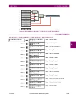
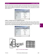
Assume the output contact H1 is a trip contact. Using the contact output settings, this output will be given an ID name; for
example, “Cont Op 1". Assume a 52a breaker auxiliary contact is connected to contact input H7a to monitor breaker status.
Using the contact input settings, this input will be given an ID name, for example, “Cont Ip 1", and will be set “On” when the
breaker is closed. The settings to use digital element 1 to monitor the breaker trip circuit are indicated below (EnerVista UR
Setup example shown):
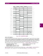
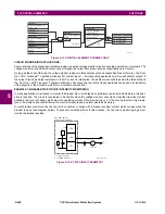
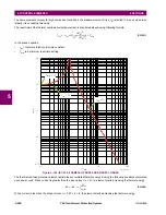
EXAMPLE 2: BREAKER TRIP CIRCUIT INTEGRITY MONITORING
If it is required to monitor the trip circuit continuously, independent of the breaker position (open or closed), a method to
maintain the monitoring current flow through the trip circuit when the breaker is open must be provided (as shown in the fig-
ure below). This can be achieved by connecting a suitable resistor (see figure below) across the auxiliary contact in the trip
circuit. In this case, it is not required to supervise the monitoring circuit with the breaker position – the
BLOCK
setting is
selected to “Off”. In this case, the settings are as follows (EnerVista UR Setup example shown).
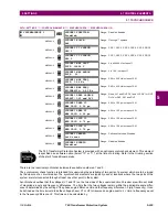
Figure 5–137: TRIP CIRCUIT EXAMPLE 2
7ULSFRLO
D
85VHULHVGHYLFH
ZLWKIRUP$FRQWDFWV
, FXUUHQWPRQLWRU
9 YROWDJHPRQLWRU
'&²
$&'5
+D
+E
+F
,
9
'&
%\SDVV
UHVLVWRU
5
3RZHUVXSSO\
5HVLVWDQFH
3RZHU
9'&
ű
:
9'&
ű
:
9'&
ű
:
9'&
ű
:
9'&
ű
:
9'&
ű
:
9DOXHVIRUUHVLVWRU´5µ
Summary of Contents for UR T60
Page 10: ...x T60 Transformer Protection System GE Multilin TABLE OF CONTENTS ...
Page 14: ...xiv T60 Transformer Protection System GE Multilin 0 1 BATTERY DISPOSAL 0 BATTERY DISPOSAL 0 ...
Page 34: ...1 20 T60 Transformer Protection System GE Multilin 1 5 USING THE RELAY 1 GETTING STARTED 1 ...
Page 436: ...5 298 T60 Transformer Protection System GE Multilin 5 10 TESTING 5 SETTINGS 5 ...
Page 678: ...C 30 T60 Transformer Protection System GE Multilin C 7 LOGICAL NODES APPENDIX C C ...
Page 688: ...D 10 T60 Transformer Protection System GE Multilin D 1 IEC 60870 5 104 PROTOCOL APPENDIX D D ...
Page 700: ...E 12 T60 Transformer Protection System GE Multilin E 2 DNP POINT LISTS APPENDIX E E ...


