


1-10
T60 Transformer Protection System
GE Multilin
1.3 ENERVISTA UR SETUP SOFTWARE
1 GETTING STARTED
1
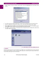
3.
Click the
Quick Connect
button to open the Quick Connect dialog box.
4.
Select the
Serial
interface and the correct COM Port, then click
Connect
.
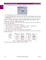
5.
The EnerVista UR Setup software will create a site named “Quick Connect” with a corresponding device also named
“Quick Connect” and display them on the upper-left corner of the screen. Expand the sections to view data directly
from the T60 device.
Each time the EnerVista UR Setup software is initialized, click the
Quick Connect
button to establish direct communica-
tions to the T60. This ensures that configuration of the EnerVista UR Setup software matches the T60 model number.
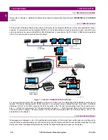
b) USING QUICK CONNECT VIA THE REAR ETHERNET PORTS
To use the Quick Connect feature to access the T60 from a computer through Ethernet, first assign an IP address to the
relay from the front panel keyboard.
1.
Press the MENU key until the SETTINGS menu is displayed.
2.
Navigate to the
SETTINGS
PRODUCT SETUP
COMMUNICATIONS
NETWORK
IP ADDRESS
setting.
3.
Enter an IP address of “1.1.1.1” and select the ENTER key to save the value.
4.
In the same menu, select the
SUBNET IP MASK
setting.
5.
Enter a subnet IP address of “255.0.0.0” and press the ENTER key to save the value.
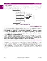
Next, use an Ethernet cross-over cable to connect the computer to the rear Ethernet port. The pinout for an Ethernet cross-
over cable is shown below.
Figure 1–6: ETHERNET CROSS-OVER CABLE PIN LAYOUT
Now, assign the computer an IP address compatible with the relay’s IP address.
842799A1.CDR
END 1
END 2
Pin
Wire color
Diagram
Pin
Wire color
Diagram
1
White/orange
1
White/green
2
Orange
2
Green
3
White/green
3
White/orange
4
Blue
4
Blue
5
White/blue
5
White/blue
6
Green
6
Orange
7
White/brown
7
White/brown
8
Brown
8
Brown
1
2
3
4 5 6
7
8
Summary of Contents for UR T60
Page 10: ...x T60 Transformer Protection System GE Multilin TABLE OF CONTENTS ...
Page 14: ...xiv T60 Transformer Protection System GE Multilin 0 1 BATTERY DISPOSAL 0 BATTERY DISPOSAL 0 ...
Page 34: ...1 20 T60 Transformer Protection System GE Multilin 1 5 USING THE RELAY 1 GETTING STARTED 1 ...
Page 436: ...5 298 T60 Transformer Protection System GE Multilin 5 10 TESTING 5 SETTINGS 5 ...
Page 678: ...C 30 T60 Transformer Protection System GE Multilin C 7 LOGICAL NODES APPENDIX C C ...
Page 688: ...D 10 T60 Transformer Protection System GE Multilin D 1 IEC 60870 5 104 PROTOCOL APPENDIX D D ...
Page 700: ...E 12 T60 Transformer Protection System GE Multilin E 2 DNP POINT LISTS APPENDIX E E ...


