


5-188
T60 Transformer Protection System
GE Multilin
5.6 GROUPED ELEMENTS
5 SETTINGS
5
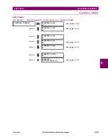
d) PHASE INSTANTANEOUS OVERCURRENT
(ANSI 50P)
PATH: SETTINGS
GROUPED ELEMENTS
SETTING GROUP 1(6)
PHASE CURRENT
PHASE IOC 1(12)
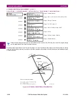
The phase instantaneous overcurrent element may be used as an instantaneous element with no intentional delay or as a
definite time element. The input current is the fundamental phasor magnitude. The phase instantaneous overcurrent timing
curves are shown below for form-A contacts in a 60 Hz system.
PHASE IOC1
PHASE IOC1
FUNCTION: Disabled
Range: Disabled, Enabled
MESSAGE
PHASE IOC1 SIGNAL
SOURCE: SRC 1
Range: SRC 1, SRC 2, SRC 3, SRC 4, SRC 5, SRC 6
MESSAGE
PHASE IOC1
PICKUP: 1.000
pu
Range: 0.000 to 30.000 pu in steps of 0.001
MESSAGE
PHASE IOC1 PICKUP
DELAY: 0.00
s
Range: 0.00 to 600.00 s in steps of 0.01
MESSAGE
PHASE IOC1 RESET
DELAY: 0.00
s
Range: 0.00 to 600.00 s in steps of 0.01
MESSAGE
PHASE IOC1 BLOCK A:
Off
Range: FlexLogic™ operand
MESSAGE
PHASE IOC1 BLOCK B:
Off
Range: FlexLogic™ operand
MESSAGE
PHASE IOC1 BLOCK C:
Off
Range: FlexLogic™ operand
MESSAGE
PHASE IOC1
TARGET: Self-reset
Range: Self-reset, Latched, Disabled
MESSAGE
PHASE IOC1
EVENTS: Disabled
Range: Disabled, Enabled
Summary of Contents for UR T60
Page 10: ...x T60 Transformer Protection System GE Multilin TABLE OF CONTENTS ...
Page 14: ...xiv T60 Transformer Protection System GE Multilin 0 1 BATTERY DISPOSAL 0 BATTERY DISPOSAL 0 ...
Page 34: ...1 20 T60 Transformer Protection System GE Multilin 1 5 USING THE RELAY 1 GETTING STARTED 1 ...
Page 436: ...5 298 T60 Transformer Protection System GE Multilin 5 10 TESTING 5 SETTINGS 5 ...
Page 678: ...C 30 T60 Transformer Protection System GE Multilin C 7 LOGICAL NODES APPENDIX C C ...
Page 688: ...D 10 T60 Transformer Protection System GE Multilin D 1 IEC 60870 5 104 PROTOCOL APPENDIX D D ...
Page 700: ...E 12 T60 Transformer Protection System GE Multilin E 2 DNP POINT LISTS APPENDIX E E ...


