


5-106
T60 Transformer Protection System
GE Multilin
5.4 SYSTEM SETUP
5 SETTINGS
5
b) BASIC CONFIGURATION
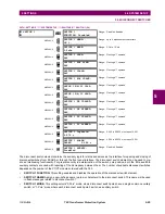
PATH: SETTINGS
SYSTEM SETUP
PHASOR...
PHASOR MEASUREMENT UNIT 1
PMU 1 BASIC CONFIGURATION 1
This section contains basic phasor measurement unit (PMU) data, such as functions, source settings, and names.
•
PMU 1 FUNCTION
: This setting enables the PMU 1 functionality. Any associated functions (such as the recorder or
triggering comparators) will not function if this setting is “Disabled”. Use the command frame to force the communica-
tion portion of the feature to start/stop transmission of data. When the transmission is turned off, the PMU is fully oper-
ational in terms of calculating and recording the phasors.
•
PMU 1 IDCODE
: This setting assigns a numerical ID to the PMU. It corresponds to the IDCODE field of the data, con-
figuration, header, and command frames of the IEEE C37.118 protocol. The PMU uses this value when sending data,
configuration, and header frames and responds to this value when receiving the command frame.
•
PMU 1 STN
: This setting assigns an alphanumeric ID to the PMU station. It corresponds to the STN field of the config-
uration frame of the IEEE C37.118 protocol. This value is a 16-character ASCII string as per the IEEE C37.118 stan-
dard.
•
PMU 1 SIGNAL SOURCE
: This setting specifies one of the available T60 signal sources for processing in the PMU.
Note that any combination of voltages and currents can be configured as a source. The current channels could be con-
figured as sums of physically connected currents. This facilitates PMU applications in breaker-and-a-half, ring-bus, and
similar arrangements. The PMU feature calculates voltage phasors for actual voltage (A, B, C, and auxiliary) and cur-
rent (A, B, C, and ground) channels of the source, as well as symmetrical components (0, 1, and 2) of both voltages
and currents. When configuring communication and recording features of the PMU, the user could select – from the
above superset – the content to be sent out or recorded.
•
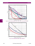
PMU 1 POST-FILTER
: This setting specifies amount of post-filtering applied to raw synchrophasor measurements.
The raw measurements are produced at the rate of nominal system frequency using one-cycle data windows. This set-
ting is provided to deal with interfering frequencies and to balance speed and accuracy of synchrophasor measure-
ments for different applications. The following filtering choices are available:
This setting applies to all channels of the PMU. It is effectively for recording and transmission on all ports configured to
use data of this PMU.
Class M filtering functionality is derived from the draft IEEE C37.118 specification and may be subject to
change when the standard is published.
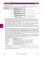
PMU 1 BASIC
CONFIGURATION
PMU 1
FUNCTION: Disabled
Range: Enabled, Disabled
MESSAGE
PMU 1 IDCODE: 1
Range: 1 to 65534 in steps of 1
MESSAGE
PMU 1 STN:
GE-UR-PMU
Range: 16 alphanumeric characters
MESSAGE
PMU 1 SIGNAL SOURCE:
SRC 1
Range: SRC 1, SRC 2, SRC 3, SRC 4, SRC 5, SRC 6
MESSAGE
PMU 1 POST-FILTER:
Symm-3-point
Range: None, Symm-3-point, Symm-5-point,
Symm-7-point, Class M, Class P
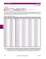
Table 5–9: POST-FILTER CHOICES
SELECTION
CHARACTERISTIC OF THE FILTER
None
No post-filtering
Symm-3-point
Symmetrical 3-point filter (1 historical point, 1 present point, 1 future point)
Symm-5-point
Symmetrical 5-point filter (2 historical points, 1 present point, 2 future points)
Symm-7-point
Symmetrical 7-point filter (3 historical points, 1 present point, 3 future points)
Class M
Symmetrical FIR filter on samples
Class P
21-tap symmetrical FIR filter on current input channels
NOTE
Summary of Contents for UR T60
Page 10: ...x T60 Transformer Protection System GE Multilin TABLE OF CONTENTS ...
Page 14: ...xiv T60 Transformer Protection System GE Multilin 0 1 BATTERY DISPOSAL 0 BATTERY DISPOSAL 0 ...
Page 34: ...1 20 T60 Transformer Protection System GE Multilin 1 5 USING THE RELAY 1 GETTING STARTED 1 ...
Page 436: ...5 298 T60 Transformer Protection System GE Multilin 5 10 TESTING 5 SETTINGS 5 ...
Page 678: ...C 30 T60 Transformer Protection System GE Multilin C 7 LOGICAL NODES APPENDIX C C ...
Page 688: ...D 10 T60 Transformer Protection System GE Multilin D 1 IEC 60870 5 104 PROTOCOL APPENDIX D D ...
Page 700: ...E 12 T60 Transformer Protection System GE Multilin E 2 DNP POINT LISTS APPENDIX E E ...


