


GE Multilin
T60 Transformer Protection System
5-117
5 SETTINGS
5.4 SYSTEM SETUP
5
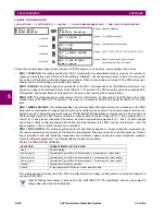
l) PMU RECORDING
PATH: SETTINGS
SYSTEM SETUP
PHASOR...
PHASOR MEASUREMENT UNIT 1
PMU 1 RECORDING
Each logical phasor measurement unit (PMU) is associated with a recorder. The triggering condition is programmed via the
PMU 1 TRIGGERING
menu. The recorder works with polar values using resolution as in the PMU actual values.
PMU 1
RECORDING
PMU 1 RECORDING
RATE: 10/sec
Range: 1, 2, 4, 5, 10, 12, 15, 20, 25, 30, 50, or 60 times
per second
MESSAGE
PMU 1 NO OF TIMED
RECORDS: 10
Range: 2 to 128 in steps of 1
MESSAGE
PMU 1 TRIGGER MODE:
Automatic Overwrite
Range: Automatic Overwrite, Protected
MESSAGE
PMU 1 TIMED TRIGGER
POSITION: 10%
Range: 1 to 50% in steps of 1
MESSAGE
PMU 1 REC PHS-1:
PMU 1 V1
Range: available synchrophasor values
MESSAGE
PMU 1 REC PHS-1
NM: GE-UR-PMU-V1
Range: 16 character ASCII string
↓
MESSAGE
PMU 1 REC PHS-14:
Off
Range: available synchrophasor values
MESSAGE
PMU 1 REC PHS-14
NM: GE-UR-PMU-PHS-14
Range: 16 character ASCII string
MESSAGE
PMU 1 REC A-CH-1:
Off
Range: available FlexAnalog values
MESSAGE
PMU 1 REC A-CH-1
NM: AnalogChannel1
Range: 16 character ASCII string
↓
MESSAGE
PMU 1 REC A-CH-8:
Off
Range: available FlexAnalog values
MESSAGE
PMU 1 REC A-CH-8
NM: AnalogChannel8
Range: 16 character ASCII string
MESSAGE
PMU 1 REC D-CH-1:
Off
Range: FlexLogic™ operand
MESSAGE
PMU 1 REC D-CH-1
NM: DigitalChannel1
Range: 16 character ASCII string
↓
MESSAGE
PMU 1 REC D-CH-16:
Off
Range: FlexLogic™ operand
MESSAGE
PMU 1 REC D-CH-16
NM: DigitalChannel16
Range: 16 character ASCII string
Summary of Contents for UR T60
Page 10: ...x T60 Transformer Protection System GE Multilin TABLE OF CONTENTS ...
Page 14: ...xiv T60 Transformer Protection System GE Multilin 0 1 BATTERY DISPOSAL 0 BATTERY DISPOSAL 0 ...
Page 34: ...1 20 T60 Transformer Protection System GE Multilin 1 5 USING THE RELAY 1 GETTING STARTED 1 ...
Page 436: ...5 298 T60 Transformer Protection System GE Multilin 5 10 TESTING 5 SETTINGS 5 ...
Page 678: ...C 30 T60 Transformer Protection System GE Multilin C 7 LOGICAL NODES APPENDIX C C ...
Page 688: ...D 10 T60 Transformer Protection System GE Multilin D 1 IEC 60870 5 104 PROTOCOL APPENDIX D D ...
Page 700: ...E 12 T60 Transformer Protection System GE Multilin E 2 DNP POINT LISTS APPENDIX E E ...


