5-382
L90 LINE CURRENT DIFFERENTIAL SYSTEM – INSTRUCTION MANUAL
CONTROL ELEMENTS
CHAPTER 5: SETTINGS
5
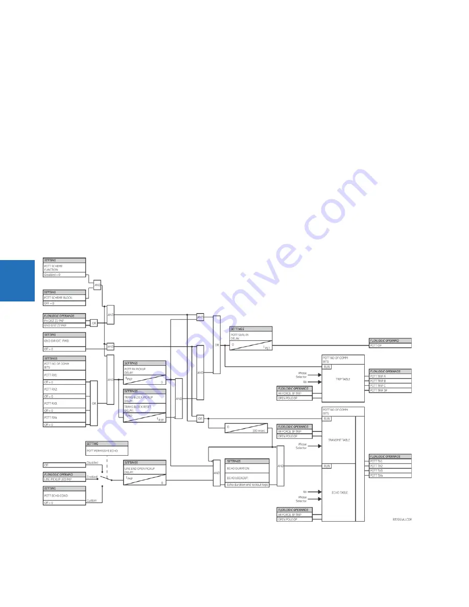
POTT SEAL-IN DELAY
— The output FlexLogic operand (
POTT OP
) is produced according to the POTT scheme logic. A seal-in
time delay is applied to this operand for coping with noisy communication channels. This setting specifies a minimum
guaranteed duration of the
POTT OP
pulse.
GND DIR O/C FWD
— This setting selects the FlexLogic operand (if any) of a protection element used in addition to zone 2 for
identifying faults on the protected line, and thus, for keying the communication channel and initiating operation of the
scheme. Good directional integrity is the key requirement for an over-reaching forward-looking protection element used as
GND DIR O/C FWD
. Even though any FlexLogic operand can be used as
GND DIR O/C FWD
allowing the user to combine
responses of various protection elements, or to apply extra conditions through FlexLogic equations, this extra signal is
primarily meant to be the output operand from either the negative-sequence directional overcurrent or neutral directional
overcurrent elements. Both of these elements have separate forward and reverse output operands. The forward indication
should be used (
NEG SEQ DIR OC1 FWD
or
NEUTRAL DIR OC1 FWD
). For greater security and to overcome spurious directional
element operation during transients, adding at least 0.5 cycles of pickup delay to the forward directional element is
recommended.
POTT RX
— This setting enables the user to select the FlexLogic operand that represents the receive signal (
RX
) for the
scheme. Typically an input contact interfacing with a signaling system is used. Other choices include remote inputs and
FlexLogic equations. The POTT transmit signal (
TX
) should be appropriately interfaced with the signaling system by
assigning the output FlexLogic operand (
POTT TX
) to an output contact. The remote output mechanism is another choice.
The output operand from the scheme (
POTT OP
) must be configured to interface with other relay functions, output contacts
in particular, in order to make the scheme fully operational. Typically, the output operand should be programmed to initiate
a trip, breaker fail, and autoreclose, and drive a user-programmable LED as per user application.
Figure 5-218: POTT scheme logic


