


AN-4#
An
alog
I
n
put
X30/12
SP-##
Spec
ia
l
Fun
ctio
ns
S
P-5#
Environment
O-1
3
C
o
nfig
u
rabl
e
Statu
s
Word
STW
O
-8#
Dr
ive
Port
Diagnostics
A
N
-40
Terminal
X
3
0
/1
2
Low
Vol
tag
e
SP-1#
L
ine
On/Of
f
SP-50
RFI
F
ilter
O-3
#
Drive
Port
Settings
O
-80
Bus
Me
ssage
Count
A
N
-41
Terminal
X
3
0
/1
2
Hig
h
Vol
tage
S
P-1
0
Lin
e
fail
u
re
S
P-51
DC
Link
Compensati
on
O-3
0
Protocol
O-8
1
Bu
s Error
Cou
n
t
A
N
-44
Ter
m.
X3
0/12
Low
Ref./Feed
b
.
Value
S
P-11
Lin
e
Vo
ltage
at
I
nput
Fault
S
P-53
F
a
n
M
o
n
it
o
r
O
-3
1 A
d
d
re
ss
O
-8
2
S
la
v
e M
e
ss
a
g
e
s
R
cv
d
A
N
-45
Ter
m.
X3
0/12
Hi
gh
Ref.
/Feedb.
Value
S
P-12
Function
at
L
ine
Imbalance
S
P-55
Output
Fi
lt
er
O-32
Dri
v
e
Po
rt
B
a
u
d
Ra
te
O
-83
S
la
v
e
Er
ro
r C
o
unt
A
N
-46
Ter
m.
X3
0/12
Fil
ter
Time
Co
nstant
SP-2#
R
eset
Func
tions
SP-59
Ac
tual
Nu
mber
of
Inverte
r
Un
its
O
-3
3
Drive
Port
Parity
O-8
9
Diag
nostics
C
o
u
nt
AN-47
Te
rm.
X30/12
Live
Z
e
ro
SP-23
Ty
p
e
code
Se
tting
SP-6#
Au
tomatic
Derate
O-3
4
Estimated
cycle
ti
me
O-
9
#
Bu
s Jo
g
/
F
e
e
d
b
a
ck
AN-5
#
A
n
a
log
O
u
tput
4
2
SP-
2
5
Tr
ip
Del
a
y
at
T
o
rq
u
e
Li
m
it
SP-60
Fu
n
ction
at
Over
Tempera
ture
O
-3
5
M
inimu
m
Respon
se
Delay
O
-9
0
Bu
s Jog
1
Speed
AN-50
Terminal
4
2
Ou
tput
SP-2
6
T
rip
Dela
y
a
t
Drive
Fau
lt
SP-61
Fu
n
ction
at
Dr
ive
Ove
rload
O-36
Maximum
R
e
sponse
De
lay
O
-91
Bus
Jog
2
Spe
e
d
A
N
-51
Terminal
4
2
Ou
tput
M
in
Sca
le
S
P-2
8
Produ
ctio
n
Set
ti
n
gs
SP-62
Dr
ive
O
v
e
rl
o
ad
De
rate
C
u
rr
ent
O
-37
Maximum
I
n
ter-C
h
ar
Del
a
y
O
-94
Bus
F
ee
d
back
1
A
N
-52
Terminal
4
2
Ou
tput
M
a
x
Scal
e
S
P-2
9
Servi
ce
Code
O-##
Options
/
Comms
O-4
#
Drive
MC
protocol
set
O-
9
5
Bu
s Fe
ed
b
a
ck
2
A
N
-53
Terminal
4
2
Ou
tput
B
u
s Control
S
P
-3
# C
u
rr
e
n
t L
im
it C
tr
l.
O
-0
#
G
e
n
e
ra
l
S
e
tt
in
g
s
O-4
0
T
e
le
g
ram
Selectio
n
O
-9
6
Bu
s Feed
back
3
A
N
-54
Terminal
4
2
Ou
tput
Ti
meou
t
Pr
ese
t
SP-30
Cur
re
nt
Lim
Ctr
l,
Pr
opo
rtio
nal
Gain
O-01
C
ontro
l
Site
O-4
2
PC
D
writ
e
config
u
ratio
n
AO-##
Anal
og
I/O
Op
ti
on
AN-6
#
A
n
a
log
O
u
tput
X3
0/8
S
P
-3
1
C
u
rr
ent
L
im
Ctrl
,
In
teg
ra
tion
T
ime
O
-02
C
o
ntro
l
W
o
rd
So
ur
ce
O
-4
3
P
C
D
re
ad
c
o
nfig
ur
atio
n
AO-0
#
Anal
og
I/O
Mode
A
N
-60
Terminal
X
3
0
/8
Ou
tput
SP-3
2
C
u
rrent
Lim
Ctrl
,
Filter
Time
O-03
Contr
o
l Word
Timeout
Time
O-5#
D
ig
ital/Bus
AO-0
0
Terminal
X4
2/1
Mo
de
A
N
-61
Terminal
X
3
0
/8
M
in.
Sca
le
SP-4#
E
n
erg
y
Savings
O-04
Contr
o
l Word
Timeout
Fun
ction
O-5
0
C
oastin
g
Sel
e
ct
AO-0
1
Terminal
X4
2/3
Mo
de
AN-62
Te
rminal
X
3
0/
8
M
a
x.
Scale
SP-40
VT
Leve
l
O-05
End-of-Ti
m
eou
t Fu
nction
O-5
2
DC
Bra
k
e
Sel
e
ct
AO-0
2
Terminal
X4
2/5
Mo
de
A
N
-63
Terminal
X
3
0
/8
Ou
tput
Bu
s
Co
ntrol
S
P-41
Energy
S
a
vings
Mi
n.
Ma
gnetiza
tion
O-06
Res
e
t Control
Wor
d
Timeou
t
O
-5
3
Start
Select
AO
-1
#
A
n
al
og
I
n
p
u
t
X42
/1
A
N
-64
Terminal
X
3
0
/8
Ou
tput
Tim
e
ou
t
Pr
ese
t
SP-42
Ener
gy
S
a
vings
Min.
Fr
eque
n
cy
O-07
Diagnosis
Tr
ig
ger
O-54
Rever
sing
Se
lec
t
A
O-10
Te
rminal
X42/1
Low
Vol
tag
e
SP-43
Motor
Cosphi
O-1#
C
o
ntrol
Se
ttings
O-5
5
Set-up
Select
AO-1
1
Terminal
X4
2/1
Hig
h
Vol
tag
e
O-10
Contr
o
l Word
Pr
ofile
O-56
Pre
set
Re
fe
rence
S
ele
ct
AO-14
Te
rm.
X42/1
Low
Re
f./
F
e
e
db.
Val
u
e
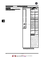
Tabl
e
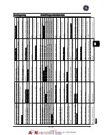
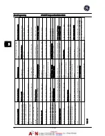
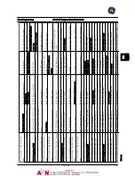
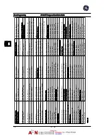
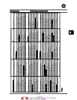
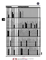
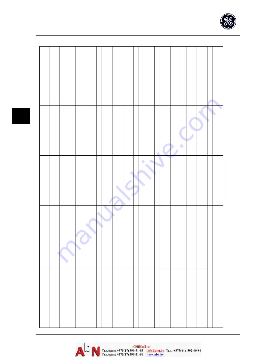
5.5
About Programming
AF-600 FP Design and Installation Guide
5-8
DET-768A
5
5
Summary of Contents for AF-600 FP Series
Page 1: ...AF 600 FPTM Fan Pump Drive Design and Installation Guide GE ...
Page 17: ...Introduction AF 600 FP Design and Installation Guide 1 10 DET 768A 1 1 ...
Page 39: ...Start Up and Functional Tes AF 600 FP Design and Installation Guide 3 6 DET 768A 3 3 ...
Page 57: ...About Programming AF 600 FP Design and Installation Guide 5 14 DET 768A 5 5 ...
Page 73: ...Application Set up Examples AF 600 FP Design and Installation Guide 6 16 DET 768A 6 6 ...
Page 83: ...Installation Consideration AF 600 FP Design and Installation Guide 7 10 DET 768A 7 7 ...
Page 87: ...Status Messages AF 600 FP Design and Installation Guide 8 4 DET 768A 8 8 ...
Page 97: ...Warnings and Alarms AF 600 FP Design and Installation Guide 9 10 DET 768A 9 9 ...
Page 101: ...Basic Troubleshooting AF 600 FP Design and Installation Guide 10 4 DET 768A 10 0 ...
Page 103: ...Terminal and Applicable Wir AF 600 FP Design and Installation Guide 11 2 DET 768A 11 1 ...


