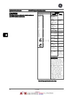
3.
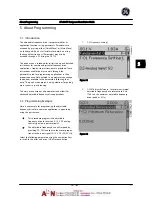
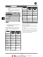
Scroll to parameter group E-0#
Digital Inputs
and
press [OK]
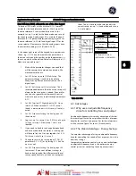
4.
Scroll to
E-01 Terminal 18 Digital Input
. Press [OK]
to access function choices. The default setting
Start
is shown.
Figure 5.11
5.4 International/North American Default
Parameter Settings
Setting
K-03 Regional Settings
to
[0] International
or
[1]
North America
changes the default settings for some
parameters.
Table 5.1
lists those parameters that are
effected.
Parameter
International
default parameter
value
North American
default parameter
value
K-03 Regional
Settings
International
North America
P-07 Motor Power
[kW]
See Note 1
See Note 1
P-02 Motor Power
[HP]
See Note 2
See Note 2
F-05 Motor Rated
Voltage
230 V/400 V/575 V
208 V/460 V/575 V
F-04 Base
Frequency
50 Hz
60 Hz
F-53 Maximum
Reference
50 Hz
60 Hz
F-54 Reference
Function
Sum
External/Preset
F-17 Motor Speed
High Limit [RPM]
See Note 3 and 5
1500 PM
1800 RPM
F-15 Motor Speed
High Limit [Hz]
See Note 4
50 Hz
60 Hz
Parameter
International
default parameter
value
North American
default parameter
value
F-03 Max Output
Frequency 1
132 Hz
120 Hz
H-73 Warning
Speed High
1500 RPM
1800 RPM
E-03 Terminal 27
Digital Input
Coast inverse
External interlock
E-24 Function Relay No operation
No alarm
AN-15 Terminal 53
High Ref./Feedb.
Value
50
60
AN-50 Terminal 42
Output
No operation
Speed 4–20 mA
H-04 Auto-Reset
(Times)
Manual reset
Infinite auto reset
Table 5.1 International/North American Default Parameter Settings
Note 1: P-07 Motor Power [kW] is only visible when K-03 Regional
Settings is set to [0] International.
Note 2: P-02 Motor Power [HP], is only visible when K-03 Regional
Settings is set to [1] North America.
Note 3: This parameter is only visible when K-02 Motor Speed Unit is
set to [0] RPM.
Note 4: This parameter is only visible when K-02 Motor Speed Unit is
set to [1] Hz.
Note 5: The default value depends on the number of motor poles. For
a 4-poled motor, the international default value is 1500 RPM, and for
a 2-poled motor, 3000 RPM. The corresponding values for North
America is 1800 and 3600 RPM, respectively.
About Programming
AF-600 FP Design and Installation Guide
5-4
DET-768A
5
5
Summary of Contents for AF-600 FP Series
Page 1: ...AF 600 FPTM Fan Pump Drive Design and Installation Guide GE ...
Page 17: ...Introduction AF 600 FP Design and Installation Guide 1 10 DET 768A 1 1 ...
Page 39: ...Start Up and Functional Tes AF 600 FP Design and Installation Guide 3 6 DET 768A 3 3 ...
Page 57: ...About Programming AF 600 FP Design and Installation Guide 5 14 DET 768A 5 5 ...
Page 73: ...Application Set up Examples AF 600 FP Design and Installation Guide 6 16 DET 768A 6 6 ...
Page 83: ...Installation Consideration AF 600 FP Design and Installation Guide 7 10 DET 768A 7 7 ...
Page 87: ...Status Messages AF 600 FP Design and Installation Guide 8 4 DET 768A 8 8 ...
Page 97: ...Warnings and Alarms AF 600 FP Design and Installation Guide 9 10 DET 768A 9 9 ...
Page 101: ...Basic Troubleshooting AF 600 FP Design and Installation Guide 10 4 DET 768A 10 0 ...
Page 103: ...Terminal and Applicable Wir AF 600 FP Design and Installation Guide 11 2 DET 768A 11 1 ...


