
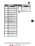


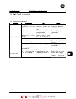


Symptom
Possible Cause
Test
Solution
Motor not running
Service switch open or missing
motor connection
Check if the motor is connected
and the connection is not
interrupted (by a service switch or
other device).
Connect the motor and check the
service switch.
No line power with 24 V DC
option card
If the display is functioning but no
output, check that line power is
applied to the adjustable frequency
drive.
Apply line power to run the unit.
keypad Stop
Check if [Off] has been pressed.
Press [Auto] or [Hand] (depending
on operation mode) to run the
motor.
Missing start signal (Standby)
Check
E-01 Terminal 18 Digital Input
for correct setting for terminal 18
(use default setting).
Apply a valid start signal to start
the motor.
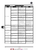
Motor coast signal active
(Coasting)
Check if a coast inv command is
programmed for the terminal in
parameter group E-0# Digital
Inputs
Apply 24 V on terminal or program
this terminal to
No operation.
Wrong reference signal source
Check reference signal: Local,
remote or bus reference? Preset
reference active? Terminal
connection correct? Scaling of
terminals correct? Reference signal
available?
Program correct settings. Check
F-02 Operation Method
. Set preset
reference active in parameter
C-05 Multi-step Frequency 1 - 8
.
Check for correct wiring. Check
scaling of terminals. Check
reference signal.
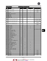
Motor running in wrong
direction
Motor rotation limit
Check that
H-08 Reverse Lock
is
programmed correctly.
Program correct settings.
Active reversing signal
Check if a reversing command is
programmed for the terminal in
parameter group
E-0# Digital inputs.
Deactivate reversing signal.
Wrong motor phase connection
See
3.5 Check Motor Rotation
in this
manual.
Motor is not reaching
maximum speed
Frequency limits set wrong
Check output limits in
F-17 Motor
Speed High Limit [RPM]
,
F-15 Motor
Speed High Limit [Hz]
and
F-03 Max
Output Frequency 1
Program correct limits.
Reference input signal not scaled
correctly
Check reference input signal
scaling in AN-## Reference limits in
parameter group F-5#.
Program correct settings.
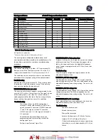
Motor speed unstable
Possible incorrect parameter
settings
Check the settings of all motor
parameters, including all motor
compensation settings. For closed-
loop operation, check PID settings.
Check settings in parameter group
AN-##. For closed-loop operation,
check settings in parameter group
CL-0#
Motor runs rough
Possible over-magnetization
Check for incorrect motor settings
in all motor parameters.
Check motor settings in parameter
groups P-0#
Motor Data
, P-3#
Adv
Motor Data
, and H-5#
Load Indep.
Setting.
Motor will not brake
Possible incorrect settings in the
brake parameters. Possible too
short ramp-down times.
Check brake parameters. Check
ramp time settings.
Check parameter group
B-0# DC
brake
and
F-5# Extended Reference
.
Basic Troubleshooting
AF-600 FP Design and Installation Guide
10-2
DET-768A
10
0
Summary of Contents for AF-600 FP Series
Page 1: ...AF 600 FPTM Fan Pump Drive Design and Installation Guide GE ...
Page 17: ...Introduction AF 600 FP Design and Installation Guide 1 10 DET 768A 1 1 ...
Page 39: ...Start Up and Functional Tes AF 600 FP Design and Installation Guide 3 6 DET 768A 3 3 ...
Page 57: ...About Programming AF 600 FP Design and Installation Guide 5 14 DET 768A 5 5 ...
Page 73: ...Application Set up Examples AF 600 FP Design and Installation Guide 6 16 DET 768A 6 6 ...
Page 83: ...Installation Consideration AF 600 FP Design and Installation Guide 7 10 DET 768A 7 7 ...
Page 87: ...Status Messages AF 600 FP Design and Installation Guide 8 4 DET 768A 8 8 ...
Page 97: ...Warnings and Alarms AF 600 FP Design and Installation Guide 9 10 DET 768A 9 9 ...
Page 101: ...Basic Troubleshooting AF 600 FP Design and Installation Guide 10 4 DET 768A 10 0 ...
Page 103: ...Terminal and Applicable Wir AF 600 FP Design and Installation Guide 11 2 DET 768A 11 1 ...


