

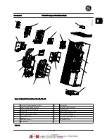
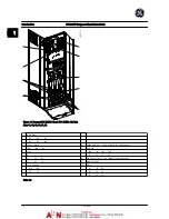
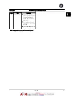

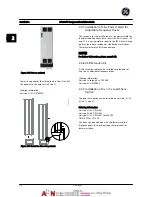
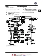

Figure 1.3 Exploded View Unit Sizes 41h, 42h, 43h, 44h
1
Local control panel mounting bracket
10
Heatsink fan
2
Control card and mounting plate
11
Gate drive support bracket
3
Power card and mounting plate
12
Capacitor bank
4
Inrush card
13
Balance/High frequency card
5
Inrush card mounting bracket
14
Motor output terminals
6
Top fan (IP20 only)
15
Line power input terminals
7
DC inductor
16
Gate drive card
8
SCR/Diode modules
17
(optional) RFI filter
9
IGBT modules
Table 1.3
Introduction
AF-600 FP Design and Installation Guide
DET-768A
1-3
1
1
Summary of Contents for AF-600 FP Series
Page 1: ...AF 600 FPTM Fan Pump Drive Design and Installation Guide GE ...
Page 17: ...Introduction AF 600 FP Design and Installation Guide 1 10 DET 768A 1 1 ...
Page 39: ...Start Up and Functional Tes AF 600 FP Design and Installation Guide 3 6 DET 768A 3 3 ...
Page 57: ...About Programming AF 600 FP Design and Installation Guide 5 14 DET 768A 5 5 ...
Page 73: ...Application Set up Examples AF 600 FP Design and Installation Guide 6 16 DET 768A 6 6 ...
Page 83: ...Installation Consideration AF 600 FP Design and Installation Guide 7 10 DET 768A 7 7 ...
Page 87: ...Status Messages AF 600 FP Design and Installation Guide 8 4 DET 768A 8 8 ...
Page 97: ...Warnings and Alarms AF 600 FP Design and Installation Guide 9 10 DET 768A 9 9 ...
Page 101: ...Basic Troubleshooting AF 600 FP Design and Installation Guide 10 4 DET 768A 10 0 ...
Page 103: ...Terminal and Applicable Wir AF 600 FP Design and Installation Guide 11 2 DET 768A 11 1 ...


