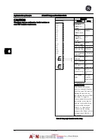


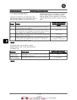


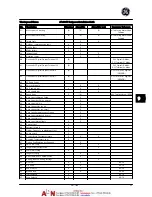

7.1.2 Emission Requirements
According to the EMC product standard for adjustable
speed adjustable frequency drives EN/IEC61800-3:2004, the
EMC requirements depend on the intended use of the
adjustable frequency drive. Four categories are defined in
the EMC product standard. The definitions of the four
categories together with the requirements for line power
supply voltage-conducted emissions are given in the table
below:
Category
Definition
Conducted emission requirement
according to the limits given in
EN55011
C1
adjustable frequency drives installed in the first environment (home and office)
with a supply voltage less than 1000 V.
Class B
C2
adjustable frequency drives installed in the first environment (home and office)
with a supply voltage of less than 1000 V, which are neither plug-in nor movable
and are intended to be installed and commissioned by a professional.
Class A Group 1
C3
adjustable frequency drives installed in the second environment (industrial) with a
supply voltage lower than 1000 V.
Class A Group 2
C4
Adjustable frequency drives installed in the second environment with a supply
voltage equal to or above 1000 V or rated current equal to or above 400 A or
intended for use in complex systems.
No limit line.
An EMC plan should be made.
Table 7.1
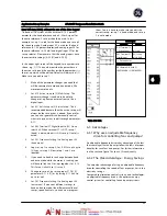
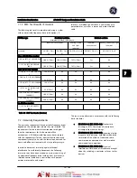
When the generic emission standards are used the
adjustable frequency drives are required to comply with
the following limits:
Environment
Generic standard
Conducted emission requirement
according to the limits given in EN55011
First environment
(home and office)
EN/IEC61000-6-3 Emission standard for residential, commercial and
light industrial environments.
Class B
Second environment
(industrial environment)
EN/IEC61000-6-4 Emission standard for industrial environments.
Class A Group 1
Table 7.2
Installation Consideration
AF-600 FP Design and Installation Guide
7-2
DET-768A
7
7
Summary of Contents for AF-600 FP Series
Page 1: ...AF 600 FPTM Fan Pump Drive Design and Installation Guide GE ...
Page 17: ...Introduction AF 600 FP Design and Installation Guide 1 10 DET 768A 1 1 ...
Page 39: ...Start Up and Functional Tes AF 600 FP Design and Installation Guide 3 6 DET 768A 3 3 ...
Page 57: ...About Programming AF 600 FP Design and Installation Guide 5 14 DET 768A 5 5 ...
Page 73: ...Application Set up Examples AF 600 FP Design and Installation Guide 6 16 DET 768A 6 6 ...
Page 83: ...Installation Consideration AF 600 FP Design and Installation Guide 7 10 DET 768A 7 7 ...
Page 87: ...Status Messages AF 600 FP Design and Installation Guide 8 4 DET 768A 8 8 ...
Page 97: ...Warnings and Alarms AF 600 FP Design and Installation Guide 9 10 DET 768A 9 9 ...
Page 101: ...Basic Troubleshooting AF 600 FP Design and Installation Guide 10 4 DET 768A 10 0 ...
Page 103: ...Terminal and Applicable Wir AF 600 FP Design and Installation Guide 11 2 DET 768A 11 1 ...


