
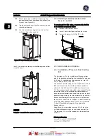
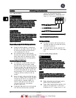


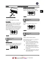


Figure 2.27 Control Wiring Access for IP55/ Nema 12 and IP66/
Nema 4X
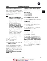
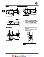
Figure 2.28 Control Card Wiring Path for Unit Size 43. Control
Card Wiring for Unit Sizes 41, 42, 44, 51 and 52 Use the Same
Path.
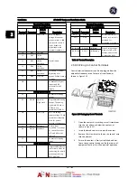
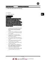
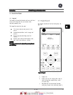
2.5.8.2 Control Terminal Types
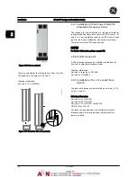
Figure 2.29
shows the removable adjustable frequency
drive connectors. Terminal functions and default settings
are summarized in
Table 2.4
.
Figure 2.29 Control Terminal Locations
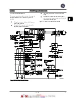
•
Connector 1 provides four programmable digital
inputs terminals, two additional digital terminals
programmable as either input or output, a 24 V
DC terminal supply voltage, and a common for
optional customer supplied 24 V DC voltage
•
Connector 2 terminals (+)68 and (-)69 are for an
RS-485 serial communications connection
•
Connector 3 provides two analog inputs, one
analog output, 10 V DC supply voltage, and
commons for the inputs and output
•
Connector 4 is a USB port available for use with
the adjustable frequency drive
•
Also provided are two Form C relay outputs that
are in various locations depending upon the
adjustable frequency drive configuration and size
•
Some options available for ordering with the unit
may provide additional terminals. See the manual
provided with the equipment option.
See
12.2 General Technical Data
for terminal ratings details.
Installation
AF-600 FP Design and Installation Guide
DET-768A
2-13
2
2
Summary of Contents for AF-600 FP Series
Page 1: ...AF 600 FPTM Fan Pump Drive Design and Installation Guide GE ...
Page 17: ...Introduction AF 600 FP Design and Installation Guide 1 10 DET 768A 1 1 ...
Page 39: ...Start Up and Functional Tes AF 600 FP Design and Installation Guide 3 6 DET 768A 3 3 ...
Page 57: ...About Programming AF 600 FP Design and Installation Guide 5 14 DET 768A 5 5 ...
Page 73: ...Application Set up Examples AF 600 FP Design and Installation Guide 6 16 DET 768A 6 6 ...
Page 83: ...Installation Consideration AF 600 FP Design and Installation Guide 7 10 DET 768A 7 7 ...
Page 87: ...Status Messages AF 600 FP Design and Installation Guide 8 4 DET 768A 8 8 ...
Page 97: ...Warnings and Alarms AF 600 FP Design and Installation Guide 9 10 DET 768A 9 9 ...
Page 101: ...Basic Troubleshooting AF 600 FP Design and Installation Guide 10 4 DET 768A 10 0 ...
Page 103: ...Terminal and Applicable Wir AF 600 FP Design and Installation Guide 11 2 DET 768A 11 1 ...


