


6.3.12 Constant Air Volume
CAV, or Constant Air Volume systems, are central
ventilation systems usually used to supply large common
zones with the minimum amounts of fresh tempered air.
They preceded VAV systems and therefore are found in
older, multi-zoned commercial buildings as well. These
systems preheat amounts of fresh air utilizing Air Handling
Units (AHUs) with a heating coil, and many are also used
to air condition buildings and have a cooling coil. Fan coil
units are frequently used to assist in the heating and
cooling requirements in the individual zones.
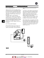
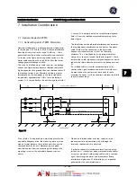
6.3.13 The AF-600 FP Solution
With an adjustable frequency drive, significant energy
savings can be obtained while maintaining decent control
of the building. Temperature sensors or CO
2
sensors can
be used as feedback signals to adjustable frequency drives.
Whether controlling temperature, air quality, or both, a
CAV system can be controlled to operate based on actual
building conditions. As the number of people in the
controlled area decreases, the need for fresh air decreases.
The CO
2
sensor detects lower levels and decreases the
supply fans speed. The return fan modulates to maintain a
static pressure setpoint or fixed difference between the
supply and return air flows.
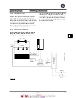
With temperature control (especially used in air
conditioning systems), as the outside temperature varies
and the number of people in the controlled zone changes,
different cooling requirements arise. As the temperature
decreases below the setpoint, the supply fan can decrease
its speed. The return fan modulates to maintain a static
pressure setpoint. By decreasing the air flow, energy used
to heat or cool the fresh air is also reduced, adding further
savings.
Several features of the GE dedicated adjustable frequency
drive can be utilized to improve the performance of your
CAV system. One concern of controlling a ventilation
system is poor air quality. The programmable minimum
frequency can be set to maintain a minimum amount of
supply air, regardless of the feedback or reference signal.
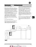
The adjustable frequency drive also includes a 3-zone, 3-
setpoint PID controller which allows monitoring of both
temperature and air quality. Even if the temperature
requirement is satisfied, the adjustable frequency drive will
maintain enough supply air to satisfy the air quality sensor.
The controller is capable of monitoring and comparing two
feedback signals to control the return fan by maintaining a
fixed differential airflow between the supply and return
ducts as well.
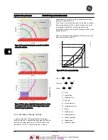
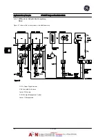
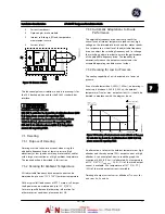
Pressure
signal
Cooling coil
Heating coil
D1
D2
D3
Filter
Pressure
transmitter
Supply fan
Return fan
Temperature
signal
Temperature
transmitter
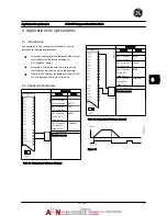
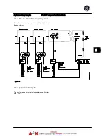
Figure 6.10
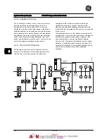
Application Set-up Examples
AF-600 FP Design and Installation Guide
DET-768A
6-11
6
6
Summary of Contents for AF-600 FP Series
Page 1: ...AF 600 FPTM Fan Pump Drive Design and Installation Guide GE ...
Page 17: ...Introduction AF 600 FP Design and Installation Guide 1 10 DET 768A 1 1 ...
Page 39: ...Start Up and Functional Tes AF 600 FP Design and Installation Guide 3 6 DET 768A 3 3 ...
Page 57: ...About Programming AF 600 FP Design and Installation Guide 5 14 DET 768A 5 5 ...
Page 73: ...Application Set up Examples AF 600 FP Design and Installation Guide 6 16 DET 768A 6 6 ...
Page 83: ...Installation Consideration AF 600 FP Design and Installation Guide 7 10 DET 768A 7 7 ...
Page 87: ...Status Messages AF 600 FP Design and Installation Guide 8 4 DET 768A 8 8 ...
Page 97: ...Warnings and Alarms AF 600 FP Design and Installation Guide 9 10 DET 768A 9 9 ...
Page 101: ...Basic Troubleshooting AF 600 FP Design and Installation Guide 10 4 DET 768A 10 0 ...
Page 103: ...Terminal and Applicable Wir AF 600 FP Design and Installation Guide 11 2 DET 768A 11 1 ...