3.4 Auto
Tune
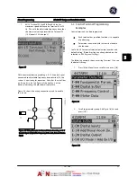
Auto tune is a test procedure that measures the electrical
characteristics of the motor to optimize compatibility
between the adjustable frequency drive and the motor.
•
The adjustable frequency drive builds a
mathematical model of the motor for regulating
output motor current. The procedure also tests
the input phase balance of electrical power. It
compares the motor characteristics with the data
entered in P-02, P-03, P-06, P-07, F-04 and F-05.
•
It does not cause the motor to run or harm to
the motor
•
Some motors may be unable to run the complete
version of the test. In that case, select
Reduced
Auto Tune
•
If an output filter is connected to the motor,
select
[2] Reduced Auto Tune
•
If warnings or alarms occur, see
9 Warnings and
Alarms
•
Run this procedure on a cold motor for best
results
3.5 Check
Motor
Rotation
Before running the adjustable frequency drive, check the
motor rotation. The motor will run briefly at 5 Hz or the
minimum frequency set in
F-16 Motor Speed Low Limit [Hz]
.
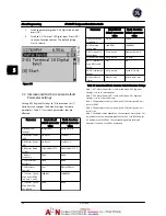
1.
Press [Main Menu] twice on the keypad.
2.
Enter Parameter Data Set and scroll to P-## Motor
Data and press [OK] to enter.
3.
Scroll to
P-08 Motor Rotation Check
.
4.
Press [OK].
5.
Scroll to
[1] Enable
.
The following text will appear:
Note! Motor may run in
wrong direction
.
6.
Press [OK].
7.
Follow the on-screen instructions.
To change the direction of rotation, remove power to the
adjustable frequency drive and wait for power to
discharge. Reverse the connection of any two of the three
motor cables on the motor or adjustable frequency drive
side of the connection.
3.6 Local
Control
Test
CAUTION
MOTOR START!
Ensure that the motor, system and any attached
equipment are ready for start. It is the responsibility of the
user to ensure safe operation under any condition. Failure
to ensure that the motor, system, and any attached
equipment are ready for start could result in personal
injury or equipment damage.
NOTE!
The [hand] key provides a local start command to the
adjustable frequency drive. The [Off] key provides the stop
function.
When operating in local mode, [
▲
] and [
▼
] increase and
decrease the speed output of the adjustable frequency
drive. [
◄
] and [
►
] move the display cursor in the numeric
display.
1.
Press [Hand].
2.
Accelerate the adjustable frequency drive by
pressing [
▲
] to full speed. Moving the cursor left
of the decimal point provides quicker input
changes.
3.
Note any acceleration problems.
4.
Press [Off].
5.
Note any deceleration problems.
If acceleration problems were encountered
•
If warnings or alarms occur, see
9 Warnings and
Alarms
.
•
Check that motor data is entered correctly.
•
Increase the accel time in
F-07 Accel Time 1
.
•
Increase current limit in
F-43 Current Limit
.
•
Increase torque limit in
F-40 Torque Limiter
(Driving)
.
If deceleration problems were encountered
•
If warnings or alarms occur, see
9 Warnings and
Alarms
.
•
Check that motor data is entered correctly.
•
Increase the decel time in
F-08 Decel Time 1
.
See
9.4 Warning and Alarm Definitions4.1.1 Local Control
Panel Keypad
for resetting the adjustable frequency drive
after a trip.
Start Up and Functional Tes...
AF-600 FP Design and Installation Guide
3-4
DET-768A
3
3
Summary of Contents for AF-600 FP Series
Page 1: ...AF 600 FPTM Fan Pump Drive Design and Installation Guide GE ...
Page 17: ...Introduction AF 600 FP Design and Installation Guide 1 10 DET 768A 1 1 ...
Page 39: ...Start Up and Functional Tes AF 600 FP Design and Installation Guide 3 6 DET 768A 3 3 ...
Page 57: ...About Programming AF 600 FP Design and Installation Guide 5 14 DET 768A 5 5 ...
Page 73: ...Application Set up Examples AF 600 FP Design and Installation Guide 6 16 DET 768A 6 6 ...
Page 83: ...Installation Consideration AF 600 FP Design and Installation Guide 7 10 DET 768A 7 7 ...
Page 87: ...Status Messages AF 600 FP Design and Installation Guide 8 4 DET 768A 8 8 ...
Page 97: ...Warnings and Alarms AF 600 FP Design and Installation Guide 9 10 DET 768A 9 9 ...
Page 101: ...Basic Troubleshooting AF 600 FP Design and Installation Guide 10 4 DET 768A 10 0 ...
Page 103: ...Terminal and Applicable Wir AF 600 FP Design and Installation Guide 11 2 DET 768A 11 1 ...

