3.
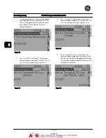
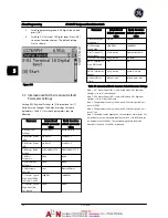
F-53 Maximum Reference
. Set maximum internal
adjustable frequency drive reference to 50 Hz.
(This sets the maximum adjustable frequency
drive speed at 60 Hz. Note that 50 Hz is a
regional variation.)
Figure 5.3
4.
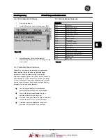
AN-10 Terminal 53 Low Voltage
. Set minimum
external voltage reference on Terminal 53 at 0 V.
(This sets the minimum input signal at 0 V.)
Figure 5.4
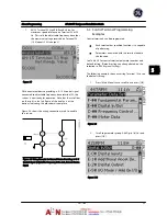
5.
AN-11 Terminal 53 High Voltage
. Set maximum
external voltage reference on Terminal 53 at 10 V.
(This sets the maximum input signal at 10 V.)
Figure 5.5
6.
AN-14 Terminal 53 Low Ref./Feedb. Value
. Set
minimum speed reference on Terminal 53 at 20
Hz. (This tells the adjustable frequency drive that
the minimum voltage received on Terminal 53 (0
V) equals 20 Hz output.)
Figure 5.6
About Programming
AF-600 FP Design and Installation Guide
5-2
DET-768A
5
5
Summary of Contents for AF-600 FP Series
Page 1: ...AF 600 FPTM Fan Pump Drive Design and Installation Guide GE ...
Page 17: ...Introduction AF 600 FP Design and Installation Guide 1 10 DET 768A 1 1 ...
Page 39: ...Start Up and Functional Tes AF 600 FP Design and Installation Guide 3 6 DET 768A 3 3 ...
Page 57: ...About Programming AF 600 FP Design and Installation Guide 5 14 DET 768A 5 5 ...
Page 73: ...Application Set up Examples AF 600 FP Design and Installation Guide 6 16 DET 768A 6 6 ...
Page 83: ...Installation Consideration AF 600 FP Design and Installation Guide 7 10 DET 768A 7 7 ...
Page 87: ...Status Messages AF 600 FP Design and Installation Guide 8 4 DET 768A 8 8 ...
Page 97: ...Warnings and Alarms AF 600 FP Design and Installation Guide 9 10 DET 768A 9 9 ...
Page 101: ...Basic Troubleshooting AF 600 FP Design and Installation Guide 10 4 DET 768A 10 0 ...
Page 103: ...Terminal and Applicable Wir AF 600 FP Design and Installation Guide 11 2 DET 768A 11 1 ...

