


CL-74
Maximum
Fe
edb
a
ck
Leve
l
X
C-
22
Ext
. 1
In
tegral
Time
XC-6
4
Ext.
3
Dif.
Gain
Limit
P
C-5
2
Al
ternati
o
n
Time
Interva
l
LC
-43
Log
ic
Ru
le
Ope
rator
2
CL
-79
PID
Aut
o
tun
ing
XC-
2
3
Ext
. 1
Diffe
re
n
tatio
n
Time
PC-##
Pump
Controller
PC-5
3
Al
ternati
on
Timer
Val
u
e
L
C
-44
Log
ic
Ru
le
Bo
olean
3
CL
-8#
P
ID
Ba
si
c
Set
tin
g
s
XC-
2
4
Ext
. 1
Dif.
Gain
Limit
PC-0
#
System
Settings
PC-54
A
lter
nation
Pr
edefined
Time
LC-5#
S
tate
s
CL
-81
PID
No
rm
a
l/
In
v
e
rs
e
Co
n
tr
o
l
XC-
3
#
Ext.
CL
2
Re
f./Fb.
PC-00
Pump
Con
tr
o
lle
r
PC-55
Alter
nate
i
f
Load
<
50%
L
C-51
Logi
c
Controll
er
Event
CL
-82
PID
Star
t Spee
d
[
R
PM]
X
C-
30
Ext
. 2
Ref
./Fe
e
dbac
k
Unit
PC-02
Mo
tor
Sta
rt
P
C-
5
6
Sta
g
in
g
Mo
de
at
Al
te
rn
ati
o
n
L
C
-52
L
o
g
ic
C
o
n
tr
o
lle
r A
cti
on
CL
-83
PID
Star
t Spee
d
[
Hz]
XC-
3
1
Ext
. 2
Minimum
R
efe
rence
P
C-04
Pu
mp
Cycl
in
g
P
C-58
R
u
n
Ne
xt
Pump
Delay
B
-##
Brakin
g
Fu
nctio
n
s
CL
-84
O
n
R
e
fe
rence
Bandw
idth
XC-
3
2
Ext
. 2
Ma
ximum
Refe
renc
e
PC-05
F
ix
e
d
Le
a
d
Pump
PC-59
R
u
n
on
L
ine
De
lay
B
-0#
DC
Brake
CL
-9#
P
ID
Co
n
tro
ller
XC-
3
3
Ext
. 2
Ref
ere
n
ce
Sour
ce
PC-06
Nu
mber
of
Pumps
PC-8#
Status
B
-0
0
D
C
H
o
ld
C
u
rr
e
n
t
CL
-91
PID
Anti
Windup
XC-
3
4
Ext
. 2
Fe
edb
a
ck
Sour
ce
PC-10
Minimum
Run
Tim
e
O
v
e
rri
d
e
PC
-8
0
Pu
m
p
S
tat
u
s
B-
0
1
DC
Br
a
ke
C
u
rre
n
t
CL
-93
PID
Pr
o
p
or
ti
onal
Gain
XC-
3
5
Ext
. 2
Se
tpo
int
PC-11
Minimum
Run
Tim
e
O
v
e
rri
d
e
V
a
lu
e
P
C
-81
Pu
m
p
S
tat
u
s
B-
0
2
DC
Br
a
ki
n
g
T
im
e
C
L
-9
4
PID
Integ
ral
Time
XC-
3
7
Ext
. 2
Ref
e
ren
ce
[Un
it]
PC-2#
B
a
ndwi
dth
S
e
ttings
PC-82
L
e
ad
Pump
B-03
DC
Br
ake
Cut
In
Spee
d
[RPM]
CL
-9
5
PID
Di
ff
e
re
n
ti
a
ti
on
T
im
e
X
C
-3
8
Ext
. 2
Fe
ed
ba
ck
[U
ni
t]
PC
-2
0
S
tag
in
g
B
a
n
d
w
id
th
P
C
-83
R
e
la
y
S
tat
u
s
B-
0
4
DC
Br
a
ke
C
ut
In
Spee
d
[
Hz]
CL
-96
PID
Diff.
Gain
Limi
t
X
C-
39
Ext
. 2
Out
p
ut
[%
]
P
C-2
1
Ov
erride
Ban
dwidth
PC-8
4
Pump
ON
Time
B-
1
#
B
rak
e
En
e
rgy
Fun
ct
.
XC-##
Ex
t.
PID
Clo
se
d
-loo
p
X
C-
4#
Ext.
CL
2
PID
P
C
-2
2
F
ix
e
d S
p
e
e
d B
a
n
d
w
id
th
P
C
-8
5
Rel
ay
ON
Time
B
-10
Brake
Fu
nct
ion
XC
-0#
Ext.
CL
Au
totun
ing
XC-
4
0
E
x
t.
2
Nor
mal
/Inv
er
se
Contr
ol
P
C-2
3
SB
W
Stag
ing
Del
ay
P
C-8
6
Reset
Rel
ay
C
ou
n
ters
B
-16
A
C
brak
e
Max.
C
u
rr
ent
XC
-00
C
losed
L
o
op
Type
XC-
4
1
Ext
. 2
Pro
p
orti
onal
Gain
PC-2
4
SB
W
Destaging
Del
a
y
PC-9#
Ser
v
ice
B-
1
7
Ov
er
-v
ol
ta
g
e
C
o
nt
ro
l
XC-01
PID
Per
forman
ce
X
C-
42
Ext
. 2
Integral
Time
PC-25
O
B
W
Time
PC-90
Pump
I
n
te
rloc
k
XC
-02
PID
Ou
tput
C
h
ang
e
XC-
4
3
Ext
.
2
Differen
tatio
n
Time
PC-2
6
Destag
e
A
t No-
F
lo
w
P
C-9
1
Manu
al
A
lterna
tion
X
C
-0
3
M
in
im
u
m
Fe
ed
b
a
ck
Le
v
e
l
X
C-
44
E
x
t.
2
D
if
. G
a
in
L
im
it
P
C-
2
7
St
a
g
e
Fu
n
ct
io
n
LC-##
Logic
Con
troller
XC-04
Max
imum
Fee
d
b
a
ck
Level
XC-
5
#
Ext.
CL
3
Re
f./Fb.
PC-28
S
tage
F
u
nction
Time
LC-0#
LC
Settings
XC
-09
PID
Au
totu
ning
XC-
5
0
Ext
. 3
Ref
./Feed
b
ack
U
nit
PC-29
D
e
stage
Func
ti
on
LC-00
L
o
gic
Co
ntr
o
lle
r Mode
XC
-1#
Ext.
CL
1
Ref
./Fb.
XC-
5
1
Ext
. 3
Mi
nimum
R
e
fe
rence
PC-30
D
e
stag
e
Fu
ncti
on
Ti
me
LC-0
1
Start
Event
XC-10
Ext.
1
Ref
./Fe
e
dback
Unit
XC-
5
2
Ext
. 3
Maximu
m
Refe
renc
e
PC-4
#
Staging
Settings
LC-02
S
top
Event
XC-11
Ext.
1
M
inimum
R
e
fe
rence
X
C-
53
Ext
. 3
Ref
e
re
n
ce
So
ur
ce
PC-40
D
e
ce
l Ramp
De
lay
LC-
03
R
e
set
Lo
gi
c
Co
nt
ro
ll
er
XC-12
Ext.
1
Maximum
Refe
rence
X
C-
54
Ext
. 3
Fe
edb
a
ck
Sour
ce
PC-41
A
cc
e
l R
a
mp
D
e
lay
LC-1
#
C
o
mparators
XC-13
Ext.
1
Ref
erenc
e
Sour
ce
XC-
5
5
Ext
. 3
Se
tpoint
PC-4
2
Sta
g
in
g
Thresh
old
L
C-1
0
Compa
rato
r
Operand
XC-14
Ext.
1
Fee
d
b
a
ck
Sour
ce
XC-
5
7
Ext
. 3
Ref
ere
n
ce
[Un
it]
PC-4
3
Destag
ing
Threshol
d
L
C-1
1
Compa
rato
r
Operator
XC
-15
Ext.
1
Setpoint
XC-
5
8
Ext
. 3
Feedb
a
ck
[Un
it]
PC-44
S
tagin
g
Spe
e
d
[RPM]
LC-12
Compar
ato
r
Value
XC
-17
Ext.
1
Ref
e
renc
e
[U
nit]
XC-
5
9
Ext
. 3
Out
p
ut
[%]
PC-45
S
tagin
g
Spe
e
d
[Hz]
LC-2#
Ti
me
rs
XC
-18
Ext.
1
Feedb
a
ck
[U
nit]
XC-
6
#
Ext.
CL
3
PID
PC-46
D
e
staging
S
p
eed
[
R
PM]
LC-20
L
o
gic
Co
ntr
o
lle
r Timer
XC
-19
E
x
t.
1
Ou
tput
[%
]
XC-
60
E
x
t.
3
Nor
mal
/Inv
er
se
Contr
ol
P
C-4
7
Destag
ing
Speed
[Hz
]
LC-4#
Logic
Rules
XC
-2#
Ext.
CL
1
PID
XC-
6
1
Ext
. 3
Pro
p
orti
onal
Gain
PC-5
#
Alternation
Settings
LC-4
0
L
o
gic
Rul
e
Bool
ean
1
XC
-20
Ext.
1
Normal/I
nv
e
rse
C
o
n
tr
o
l
X
C
-6
2
E
x
t.
3
In
te
g
ra
l T
im
e
P
C
-5
0
L
e
a
d P
u
m
p
A
lt
e
rn
a
ti
o
n
L
C
-4
1
L
o
g
ic
R
u
le
O
p
e
ra
to
r 1
XC
-21
Ext.
1
Proportional
Gain
XC-
6
3
Ext
. 3
Differen
tatio
n
Time
PC-5
1
Al
ternati
on
Even
t
L
C-4
2
Lo
gic
Rul
e
Bool
ean
2
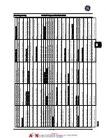
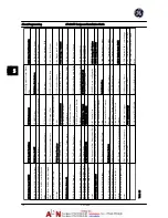
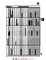
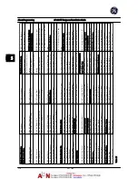
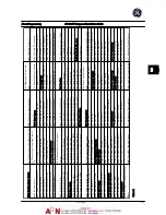
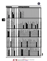
Tabl
e
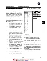
5.9
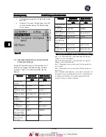
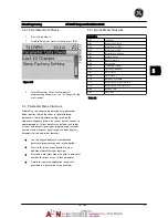
About Programming
AF-600 FP Design and Installation Guide
5-12
DET-768A
5
5
Summary of Contents for AF-600 FP Series
Page 1: ...AF 600 FPTM Fan Pump Drive Design and Installation Guide GE ...
Page 17: ...Introduction AF 600 FP Design and Installation Guide 1 10 DET 768A 1 1 ...
Page 39: ...Start Up and Functional Tes AF 600 FP Design and Installation Guide 3 6 DET 768A 3 3 ...
Page 57: ...About Programming AF 600 FP Design and Installation Guide 5 14 DET 768A 5 5 ...
Page 73: ...Application Set up Examples AF 600 FP Design and Installation Guide 6 16 DET 768A 6 6 ...
Page 83: ...Installation Consideration AF 600 FP Design and Installation Guide 7 10 DET 768A 7 7 ...
Page 87: ...Status Messages AF 600 FP Design and Installation Guide 8 4 DET 768A 8 8 ...
Page 97: ...Warnings and Alarms AF 600 FP Design and Installation Guide 9 10 DET 768A 9 9 ...
Page 101: ...Basic Troubleshooting AF 600 FP Design and Installation Guide 10 4 DET 768A 10 0 ...
Page 103: ...Terminal and Applicable Wir AF 600 FP Design and Installation Guide 11 2 DET 768A 11 1 ...


