

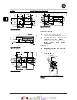


Figure 2.31 Connecting Control Wiring
2.5.8.4 Using Shielded Control Cables
Correct shielding
The preferred method in most cases is to secure control
and serial communication cables with shielding clamps
provided at both ends to ensure best possible high
frequency cable contact.
If the ground potential between the adjustable frequency
drive and the PLC is different, electrical noise may occur
that will disturb the entire system. Solve this problem by
fitting an equalizing cable next to the control cable.
Minimum cable cross-section: 0.025 in
2
(16 mm
2)
.
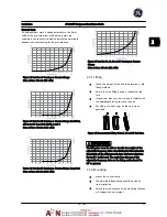
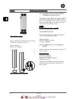
Figure 2.32
1
Min. 0.025 in
2
[16 mm
2
]
2
Equalizing cable
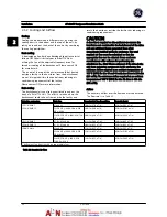
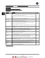
Table 2.5
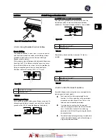
50/60 Hz ground loops
With very long control cables, ground loops may occur. To
eliminate ground loops, connect one end of the shield-to-
ground with a 100 nF capacitor (keeping leads short).
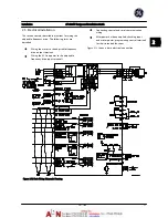
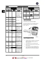
Figure 2.33
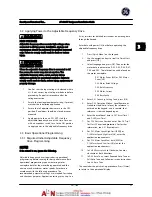
Avoid EMC noise on serial communication
This terminal is grounded via an internal RC link. Use
twisted-pair cables to reduce interference between
conductors. The recommended method is shown below:
Figure 2.34
1
Min. 0.025 in
2
[16 mm
2
]
2
Equalizing cable
Table 2.6
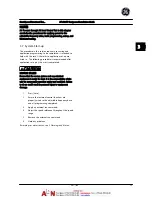
Alternatively, the connection to terminal 61 can be
omitted:
Figure 2.35
1
Min. 0.025 in
2
[16 mm
2
]
2
Equalizing cable
Table 2.7
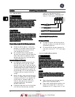
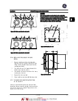
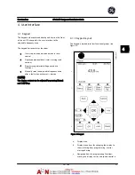
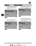
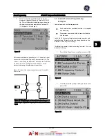
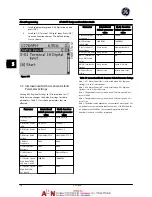
2.5.8.5 Control Terminal Functions
Adjustable frequency drive functions are commanded by
receiving control input signals.
•
Each terminal must be programmed for the
function it will be supporting in the parameters
associated with that terminal. See
Table 2.4
for
terminals and associated parameters.
•
It is important to confirm that the control
terminal is programmed for the correct function.
See
4 User Interface
for details on accessing
parameters and
5 About Programming
for details
on programming.
•
The default terminal programming is intended to
initiate adjustable frequency drive functioning in
a typical operational mode.
Installation
AF-600 FP Design and Installation Guide
DET-768A
2-15
2
2
Summary of Contents for AF-600 FP Series
Page 1: ...AF 600 FPTM Fan Pump Drive Design and Installation Guide GE ...
Page 17: ...Introduction AF 600 FP Design and Installation Guide 1 10 DET 768A 1 1 ...
Page 39: ...Start Up and Functional Tes AF 600 FP Design and Installation Guide 3 6 DET 768A 3 3 ...
Page 57: ...About Programming AF 600 FP Design and Installation Guide 5 14 DET 768A 5 5 ...
Page 73: ...Application Set up Examples AF 600 FP Design and Installation Guide 6 16 DET 768A 6 6 ...
Page 83: ...Installation Consideration AF 600 FP Design and Installation Guide 7 10 DET 768A 7 7 ...
Page 87: ...Status Messages AF 600 FP Design and Installation Guide 8 4 DET 768A 8 8 ...
Page 97: ...Warnings and Alarms AF 600 FP Design and Installation Guide 9 10 DET 768A 9 9 ...
Page 101: ...Basic Troubleshooting AF 600 FP Design and Installation Guide 10 4 DET 768A 10 0 ...
Page 103: ...Terminal and Applicable Wir AF 600 FP Design and Installation Guide 11 2 DET 768A 11 1 ...


