

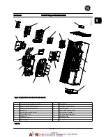
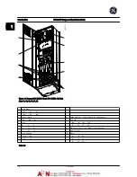
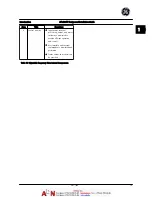

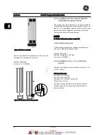
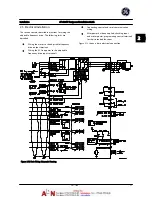


Figure 1.7 Inverter Cabinet, Unit Sizes 62 and 64
(Unit Sizes 61 and 63 are similar with two inverter modules)
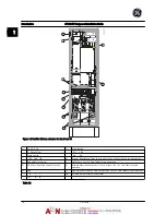
1)
External Temperature Monitoring
6)
Motor
2)
AUX Relay
U
V
W
01
02
03
96
97
98
04
05
06
T1
T2
T3
4)
AUX Fan
8)
Fan Fuses. See
12.3 Fuse Tables
for part numbers
100
101 102 103
9)
SMPS
Fuses.
See
12.3 Fuse Tables
for part numbers
L1
L2
L1
L2
Table 1.6
Introduction
AF-600 FP Design and Installation Guide
DET-768A
1-7
1
1
Summary of Contents for AF-600 FP Series
Page 1: ...AF 600 FPTM Fan Pump Drive Design and Installation Guide GE ...
Page 17: ...Introduction AF 600 FP Design and Installation Guide 1 10 DET 768A 1 1 ...
Page 39: ...Start Up and Functional Tes AF 600 FP Design and Installation Guide 3 6 DET 768A 3 3 ...
Page 57: ...About Programming AF 600 FP Design and Installation Guide 5 14 DET 768A 5 5 ...
Page 73: ...Application Set up Examples AF 600 FP Design and Installation Guide 6 16 DET 768A 6 6 ...
Page 83: ...Installation Consideration AF 600 FP Design and Installation Guide 7 10 DET 768A 7 7 ...
Page 87: ...Status Messages AF 600 FP Design and Installation Guide 8 4 DET 768A 8 8 ...
Page 97: ...Warnings and Alarms AF 600 FP Design and Installation Guide 9 10 DET 768A 9 9 ...
Page 101: ...Basic Troubleshooting AF 600 FP Design and Installation Guide 10 4 DET 768A 10 0 ...
Page 103: ...Terminal and Applicable Wir AF 600 FP Design and Installation Guide 11 2 DET 768A 11 1 ...


