


6.3.14 Cooling Tower Fan
Cooling tower fans are used to cool condenser water in
water-cooled chiller systems. Water-cooled chillers provide
the most efficient means of creating chilled water. They
are as much as 20% more efficient than air-cooled chillers.
Depending on climate, cooling towers are often the most
energy efficient method of cooling the condenser water
from chillers.
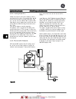
They cool the condenser water by evaporation.
The condenser water is sprayed into the cooling tower,
onto the cooling tower's “fill” to increase its surface area.
The tower fan blows air through the fill and sprayed water
to aid in the evaporation. Evaporation removes energy
from the water, thus dropping its temperature. The cooled
water collects in the cooling towers basin, where it is
pumped back into the chiller's condenser, and the cycle is
then repeated.
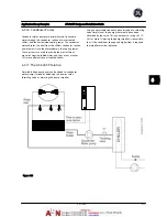
6.3.15 The AF-600 FP Solution
With an adjustable frequency drive, the cooling towers
fans can be set to the speed required to maintain the
condenser water temperature. The adjustable frequency
drives can also be used to turn the fan on and off as
needed.
Several features of the GE dedicated adjustable frequency
drive can be utilized to improve the performance of your
cooling tower fans application. As the cooling tower fans
drop below a certain speed, the effect the fan has on
cooling the water becomes insignificant. Also, when
utilizing a gear box to frequency control the tower fan, a
minimum speed of 40-50% may be required.
The customer programmable minimum frequency setting
is available to maintain this minimum frequency even as
the feedback or speed reference calls for lower speeds.
Another standard feature is the “sleep” mode, which allows
the user to program the adjustable frequency drive to stop
the fan until a higher speed is required. Additionally, some
cooling tower fans have undesireable frequencies that may
cause vibrations. These frequencies can easily be avoided
by programming the bypass frequency ranges in the
adjustable frequency drive.
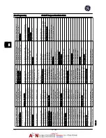
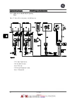
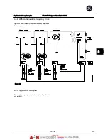
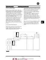
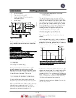
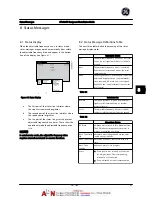
Figure 6.11
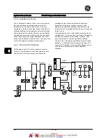
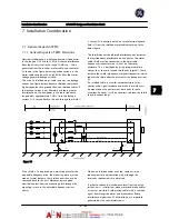
Application Set-up Examples
AF-600 FP Design and Installation Guide
6-12
DET-768A
6
6
Summary of Contents for AF-600 FP Series
Page 1: ...AF 600 FPTM Fan Pump Drive Design and Installation Guide GE ...
Page 17: ...Introduction AF 600 FP Design and Installation Guide 1 10 DET 768A 1 1 ...
Page 39: ...Start Up and Functional Tes AF 600 FP Design and Installation Guide 3 6 DET 768A 3 3 ...
Page 57: ...About Programming AF 600 FP Design and Installation Guide 5 14 DET 768A 5 5 ...
Page 73: ...Application Set up Examples AF 600 FP Design and Installation Guide 6 16 DET 768A 6 6 ...
Page 83: ...Installation Consideration AF 600 FP Design and Installation Guide 7 10 DET 768A 7 7 ...
Page 87: ...Status Messages AF 600 FP Design and Installation Guide 8 4 DET 768A 8 8 ...
Page 97: ...Warnings and Alarms AF 600 FP Design and Installation Guide 9 10 DET 768A 9 9 ...
Page 101: ...Basic Troubleshooting AF 600 FP Design and Installation Guide 10 4 DET 768A 10 0 ...
Page 103: ...Terminal and Applicable Wir AF 600 FP Design and Installation Guide 11 2 DET 768A 11 1 ...


