


•
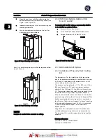
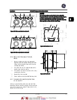
Mount the unit to a solid flat surface or to the
optional backplate to provide cooling airflow (see
Figure 2.7
and
Figure 2.8
).
•
Improper mounting can result in overheating and
reduced performance.
•
Use the slotted mounting holes on the unit for
wall mounting, when provided.
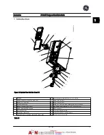
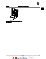
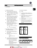
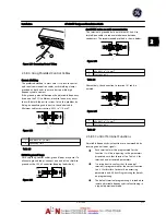
Figure 2.7 Proper Mounting with Backplate
Item A is a backplate properly installed for required airflow
to cool the unit.
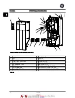
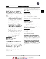
Figure 2.8 Proper Mounting with Railings
NOTE!
Backplate is needed when mounted on railings.
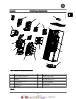
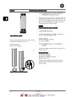
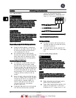
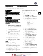
2.3.5 IP21 Drip Shield Installation (Unit
Sizes 41 and 42)
To comply with the IP21 rating, a separate drip shield is
to be installed as explained below:
•
Remove the two front screws.
•
Insert the drip shield and replace the screws.
•
Torque the screws to 5.6 Nm (50 in-lbs).
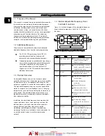
Figure 2.9 Install the drip shield.
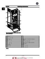
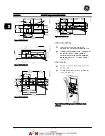
2.4 Field Installation of Options
2.4.1 Installation of Top-only Duct Cooling
Kit
This description is for the installation of the top section
only of the backchannel cooling kits available for unit sizes
43, 44 and 52. In addition to the enclosure, an 8 in [200
mm] vented pedestal is required.
The minimum enclosure depth is 19.7 in [500 mm] (23.6 in
[600 mm] for unit size 52) and the minimum enclosure
width is 23.6 in [600 mm] (31.5 in [800 mm] for unit size
52). The maximum depth and width are as required for the
installation. When using multiple adjustable frequency
drives in one enclosure mount each drive on its own back
panel and support along the mid-section of the panel. The
back-channel cooling kits are very similar in construction
for all frames. The kits do not support “in frame” mounting
of the adjustable frequency drives. The 52 kit is mounted
“in frame” for additional support of the adjustable
frequency drive.
Using these kits as described removes 85% of the losses
via the backchannel using the drive’s main heatsink fan.
The remaining 15% must be removed via the door of the
enclosure.
Ordering information
Unit size 43 and 44: OPCDUCT4344T
Unit size 52: OPCDUCT52T
Installation
AF-600 FP Design and Installation Guide
2-4
DET-768A
2
2
Summary of Contents for AF-600 FP Series
Page 1: ...AF 600 FPTM Fan Pump Drive Design and Installation Guide GE ...
Page 17: ...Introduction AF 600 FP Design and Installation Guide 1 10 DET 768A 1 1 ...
Page 39: ...Start Up and Functional Tes AF 600 FP Design and Installation Guide 3 6 DET 768A 3 3 ...
Page 57: ...About Programming AF 600 FP Design and Installation Guide 5 14 DET 768A 5 5 ...
Page 73: ...Application Set up Examples AF 600 FP Design and Installation Guide 6 16 DET 768A 6 6 ...
Page 83: ...Installation Consideration AF 600 FP Design and Installation Guide 7 10 DET 768A 7 7 ...
Page 87: ...Status Messages AF 600 FP Design and Installation Guide 8 4 DET 768A 8 8 ...
Page 97: ...Warnings and Alarms AF 600 FP Design and Installation Guide 9 10 DET 768A 9 9 ...
Page 101: ...Basic Troubleshooting AF 600 FP Design and Installation Guide 10 4 DET 768A 10 0 ...
Page 103: ...Terminal and Applicable Wir AF 600 FP Design and Installation Guide 11 2 DET 768A 11 1 ...


