
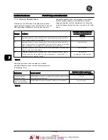


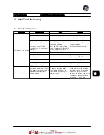

8 Status Messages
8.1 Status
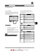
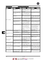
Display
When the adjustable frequency drive is in status mode,
status messages are generated automatically from within
the adjustable frequency drive and appear in the bottom
line of the display (see
Figure 8.1
.)
Figure 8.1 Status Display
a.
The first part of the status line indicates where
the stop/start command originates.
b.
The second part of the status line indicates where
the speed control originates.
c.
The last part of the status line gives the present
adjustable frequency drive status. These show the
operational mode the adjustable frequency drive
is in.
NOTE!
In auto/remote mode, the adjustable frequency drive
requires external commands to execute functions.
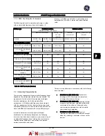
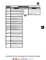
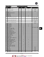
8.2 Status Message Definitions Table
The next three tables define the meaning of the status
message display words.
Operation
Mode
Off
The adjustable frequency drive does not react
to any control signal until [Auto] or [Hand] is
pressed.
Auto
The adjustable frequency drive is controlled
from the control terminals and/or the serial
communication.
Hand
The navigation keys on the keypad control the
adjustable frequency drive. Stop commands,
reset, reversing, DC brake, and other signals
applied to the control terminals can override
local control.
Table 8.1
Reference Site
Remote
The speed reference is given from external
signals, serial communication, or internal
preset references.
Local
The adjustable frequency drive uses [Hand]
control or reference values from the keypad.
Table 8.2
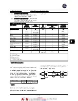
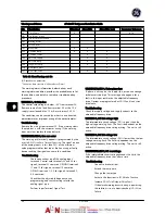
Operation
Status
AC Brake
AC Brake was selected in
B-10 Brake Function
.
The AC brake over-magnetizes the motor to
achieve a controlled slow down.
Auto Tune finish
OK
Automatic motor adaptation Auto tune was
carried out successfully.
Auto Tune ready Auto tune is ready to start. Press [Hand] to
start.
Auto Tune
running
Auto tune process is in progress.
Coast
•
Coast inverse was selected as a function
for a digital input. The corresponding
terminal is not connected.
•
Coast activated by serial communication
Status Messages
AF-600 FP Design and Installation Guide
DET-768A
8-1
8
8
Summary of Contents for AF-600 FP Series
Page 1: ...AF 600 FPTM Fan Pump Drive Design and Installation Guide GE ...
Page 17: ...Introduction AF 600 FP Design and Installation Guide 1 10 DET 768A 1 1 ...
Page 39: ...Start Up and Functional Tes AF 600 FP Design and Installation Guide 3 6 DET 768A 3 3 ...
Page 57: ...About Programming AF 600 FP Design and Installation Guide 5 14 DET 768A 5 5 ...
Page 73: ...Application Set up Examples AF 600 FP Design and Installation Guide 6 16 DET 768A 6 6 ...
Page 83: ...Installation Consideration AF 600 FP Design and Installation Guide 7 10 DET 768A 7 7 ...
Page 87: ...Status Messages AF 600 FP Design and Installation Guide 8 4 DET 768A 8 8 ...
Page 97: ...Warnings and Alarms AF 600 FP Design and Installation Guide 9 10 DET 768A 9 9 ...
Page 101: ...Basic Troubleshooting AF 600 FP Design and Installation Guide 10 4 DET 768A 10 0 ...
Page 103: ...Terminal and Applicable Wir AF 600 FP Design and Installation Guide 11 2 DET 768A 11 1 ...


