


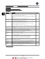


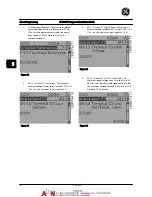

Terminal Description
Digital Inputs/Outputs
Terminal
Parameter
Default
Setting
Description
12, 13
-
+24 V DC
24 V DC supply
voltage. Maximum
output current is 200
mA total for all 24 V
loads. Usable for
digital inputs and
external transducers.
18
E-01
[8] Start
Digital inputs.
19
E-02
[0] No
operation
32
E-05
[0] No
operation
33
E-06
[0] No
operation
27
E-03
[0] No
operation
Selectable for either
digital input or
output. Default setting
is input.
29
E-04
[14] JOG
20
-
Common
for
digital
inputs and 0 V
potential for 24 V
supply.
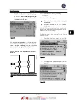
Analog Inputs/Outputs
39
-
Common for analog
output
42
AN-50
Speed 0 -
High Limit
Programmable analog
output. The analog
signal is 0–20 mA or
4-20 mA at a
maximum of 500
Ω
50
-
+10 V DC
10 V DC analog
supply voltage. 15 mA
maximum commonly
used for potenti-
ometer or thermistor.
53
AN-1#
Reference
Analog input.
Selectable for voltage
or current. Switches
A53 and A54 select
mA or V.
54
AN-2#
Feedback
55
-
Common for analog
input
Serial Communication
61
-
Integrated RC filter for
cable shield. ONLY for
connecting the shield
when experiencing
EMC problems.
Terminal Description
Digital Inputs/Outputs
Terminal
Parameter
Default
Setting
Description
68 (+)
O-3#
RS-485 Interface. A
control card switch is
provided for
termination resistance.
69 (-)
O-3#
Relays
01, 02, 03
E-24 [0]
[0] Alarm
Form C relay output.
Usable for AC or DC
voltage and resistive
or inductive loads.
04, 05, 06
E-24 [1]
[0] Running
Table 2.4 Terminal Description
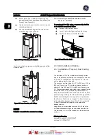
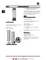
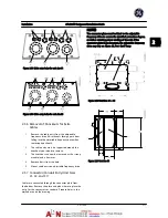
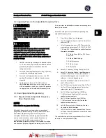
2.5.8.3 Wiring to Control Terminals
Control terminal connectors can be unplugged from the
adjustable frequency drive for ease of installation, as
shown in
Figure 2.30
.
Figure 2.30 Unplugging Control Terminals
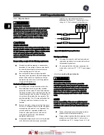
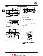
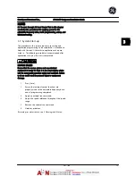
1.
Open the contact by inserting a small screwdriver
into the slot above or below the contact, as
shown in
Figure 2.31
.
2.
Insert the bared control wire into the contact.
3.
Remove the screwdriver to fasten the control wire
into the contact.
4.
Ensure the contact is firmly established and not
loose. Loose control wiring can be the source of
equipment faults or less than optimal operation.
Installation
AF-600 FP Design and Installation Guide
2-14
DET-768A
2
2
Summary of Contents for AF-600 FP Series
Page 1: ...AF 600 FPTM Fan Pump Drive Design and Installation Guide GE ...
Page 17: ...Introduction AF 600 FP Design and Installation Guide 1 10 DET 768A 1 1 ...
Page 39: ...Start Up and Functional Tes AF 600 FP Design and Installation Guide 3 6 DET 768A 3 3 ...
Page 57: ...About Programming AF 600 FP Design and Installation Guide 5 14 DET 768A 5 5 ...
Page 73: ...Application Set up Examples AF 600 FP Design and Installation Guide 6 16 DET 768A 6 6 ...
Page 83: ...Installation Consideration AF 600 FP Design and Installation Guide 7 10 DET 768A 7 7 ...
Page 87: ...Status Messages AF 600 FP Design and Installation Guide 8 4 DET 768A 8 8 ...
Page 97: ...Warnings and Alarms AF 600 FP Design and Installation Guide 9 10 DET 768A 9 9 ...
Page 101: ...Basic Troubleshooting AF 600 FP Design and Installation Guide 10 4 DET 768A 10 0 ...
Page 103: ...Terminal and Applicable Wir AF 600 FP Design and Installation Guide 11 2 DET 768A 11 1 ...


