


7 Installation Consideration
7.1 General Aspects of EMC
7.1.1 General Aspects of EMC Emissions
Electrical interference is usually conducted at frequencies
in the range of 150 kHz to 30 MHz. Airborne interference
from the drive system in the range 30 MHz to 1 GHz is
generated from the inverter, motor cable, and the motor.
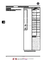
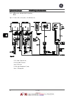
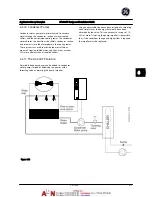
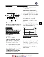
As shown in the figure below, capacitive currents in the
motor cable coupled with a high dV/dt from the motor
voltage generate leakage currents.
The use of a shielded motor cable increases the leakage
current (see figure below), because shielded cables have
higher capacitance to ground than non-shielded cables. If
the leakage current is not filtered, it will cause greater
interference on the line power in the radio frequency
range below approximately 5 MHz. Since the leakage
current (I
1
) is carried back to the unit through the shield (I
3
), there will in principle only be a small electro-magnetic
field (I
4
) from the shielded motor cable according to the
below figure.
The shield reduces the radiated interference but increases
the low-frequency interference on line power. The motor
cable shield must be connected to the adjustable
frequency drive enclosure as well as on the motor
enclosure. This is best done by using integrated shield
clamps so as to avoid twisted shield ends (pigtails). These
increase the shield impedance at higher frequencies, which
reduces the shield effect and increases the leakage current
(I
4
).
If a shielded cable is used for networknetwork, relay,
control cable, signal interface and brake, the shield must
be mounted on the enclosure at both ends. In some
situations, however, it will be necessary to break the shield
to avoid current loops.
Figure 7.1
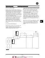
If the shield is to be placed on a mounting plate for the
adjustable frequency drive, the mounting plate must be
made of metal, because the shield currents have to be
conveyed back to the unit. Moreover, ensure good
electrical contact from the mounting plate through the
mounting screws to the adjustable frequency driver
chassis.
When non-shielded cables are used, some emission
requirements are not complied with, although the
immunity requirements are observed.
In order to reduce the interference level from the entire
system (unit + installation), make motor and brake cables
as short as possible. Avoid placing cables with a sensitive
signal level alongside motor and brake cables. Radio
interference higher than 50 MHz (airborne) is especially
generated by the control electronics.
Installation Consideration
AF-600 FP Design and Installation Guide
DET-768A
7-1
7
7
Summary of Contents for AF-600 FP Series
Page 1: ...AF 600 FPTM Fan Pump Drive Design and Installation Guide GE ...
Page 17: ...Introduction AF 600 FP Design and Installation Guide 1 10 DET 768A 1 1 ...
Page 39: ...Start Up and Functional Tes AF 600 FP Design and Installation Guide 3 6 DET 768A 3 3 ...
Page 57: ...About Programming AF 600 FP Design and Installation Guide 5 14 DET 768A 5 5 ...
Page 73: ...Application Set up Examples AF 600 FP Design and Installation Guide 6 16 DET 768A 6 6 ...
Page 83: ...Installation Consideration AF 600 FP Design and Installation Guide 7 10 DET 768A 7 7 ...
Page 87: ...Status Messages AF 600 FP Design and Installation Guide 8 4 DET 768A 8 8 ...
Page 97: ...Warnings and Alarms AF 600 FP Design and Installation Guide 9 10 DET 768A 9 9 ...
Page 101: ...Basic Troubleshooting AF 600 FP Design and Installation Guide 10 4 DET 768A 10 0 ...
Page 103: ...Terminal and Applicable Wir AF 600 FP Design and Installation Guide 11 2 DET 768A 11 1 ...


