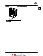

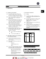
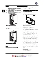


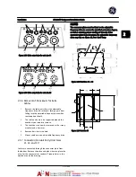

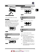


Figure 2.10 Drive on pedestal
There is one pedestal that fits both Unit Sizes 41 and 42.
The pedestal is standard for Unit Size 51.
Ordering information
Unit size 41/42: OPC4XPED
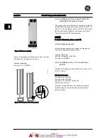
Figure 2.11 Mount the drive onto pedestal.
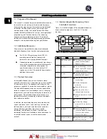
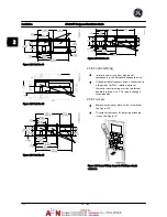
2.4.7 Installation of Line Power Shield for
Adjustable Frequency Drives
This section is for the installation of a line power shield for
the adjustable frequency drive series with Unit Sizes 41, 42
and 51. It is not possible to install in the IP00/ chassis drive
types as these have included as standard a metal cover.
These shields satisfy VBG-4 requirements.
NOTE!
For further information, please consult GE.
2.4.8 USB Extension Kit
A USB extension cable can be installed into the door of
unit size 6x adjustable frequency drives.
Ordering information
Unit size 1x through 5x: OPCUSB
Unit size 6x: OPCUSB6X
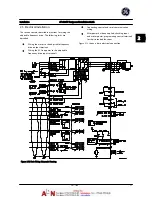
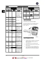
2.4.9 Installation of 4x or 5x Load Share
Option
The load share option can be installed on unit sizes 41, 42,
43, 44, 51 and 52.
Ordering information
Unit size 41/43: OPCLSK41
Unit size 42/44: OPCLSK42
Unit size 51/52: OPCLSK51 for 460 VAC
OPCLSK52 for 575 VAC
The drive can be purchased with the factory-installed
brake chopper which includes load share terminals as
factory installed.
Installation
AF-600 FP Design and Installation Guide
2-6
DET-768A
2
2
Summary of Contents for AF-600 FP Series
Page 1: ...AF 600 FPTM Fan Pump Drive Design and Installation Guide GE ...
Page 17: ...Introduction AF 600 FP Design and Installation Guide 1 10 DET 768A 1 1 ...
Page 39: ...Start Up and Functional Tes AF 600 FP Design and Installation Guide 3 6 DET 768A 3 3 ...
Page 57: ...About Programming AF 600 FP Design and Installation Guide 5 14 DET 768A 5 5 ...
Page 73: ...Application Set up Examples AF 600 FP Design and Installation Guide 6 16 DET 768A 6 6 ...
Page 83: ...Installation Consideration AF 600 FP Design and Installation Guide 7 10 DET 768A 7 7 ...
Page 87: ...Status Messages AF 600 FP Design and Installation Guide 8 4 DET 768A 8 8 ...
Page 97: ...Warnings and Alarms AF 600 FP Design and Installation Guide 9 10 DET 768A 9 9 ...
Page 101: ...Basic Troubleshooting AF 600 FP Design and Installation Guide 10 4 DET 768A 10 0 ...
Page 103: ...Terminal and Applicable Wir AF 600 FP Design and Installation Guide 11 2 DET 768A 11 1 ...