


AP-3#
No-Flow
Power
Tun
ing
A
P-71
Compr
e
ssor
Star
t Max
Spe
e
d
[H
z]
F
B
-09
Fire
M
o
de
Ala
rm
Handling
T-
14
Ma
inten
ance
Da
te
a
n
d
Ti
me
C
L
-0
3
F
e
edb
a
ck
2
So
ur
ce
AP-30
No-Flow
Pow
e
r
AP-7
2
Co
mpressor
Start
Max
Time
to
Tri
p
FB
-1
#
D
ri
v
e
B
y
p
a
ss
T-
15
Re
set
Maintenance
Wor
d
CL-04
Fee
d
b
a
ck
2
Con
v
er
sion
AP-3
1
Power
Co
rrection
F
a
ct
or
AP-7
3
St
a
rting
Acceleration
Time
F
B
-1
0
Driv
e
Bypass
Fu
nct
ion
T-
16
Ma
inten
a
nce
Text
C
L
-05
Feedb
a
ck
2
S
ou
rc
e
U
n
it
AP-32
L
o
w
Spe
e
d
[R
PM
]
A
P-75
Shor
t
Cyc
le
Prote
ctio
n
F
B
-11
Dr
iv
e
Bypass
Delay
Time
T-
5#
Energ
y
Log
C
L
-0
6
F
e
edb
a
ck
3
So
ur
ce
AP-3
3
L
o
w
Speed
[Hz]
AP-7
6
I
n
terval
betw
een
Starts
F
B
-20
Locked
Ro
tor
Fu
nctio
n
T-
50
Energy
Log
Reso
luti
o
n
CL-0
7
Fee
d
ba
ck
3
C
o
nver
si
on
AP-34
L
o
w
Spe
e
d
Power
[
k
W]
AP-77
Mini
mum
Run
Ti
me
F
B
-21
Locked
R
o
to
r Coe
ffi
ci
ent
1
T
-5
1
Per
iod
St
ar
t
C
L-08
Fee
d
b
a
ck
3
S
o
urc
e
Un
it
AP-35
L
o
w
Spe
e
d
Power
[
HP]
AP-8
#
Fl
ow
C
o
mpensation
F
B
-22
Locked
R
o
tor
Coe
ffi
ci
ent
2
T
-5
3
Ene
rgy
Log
C
L-12
Ref
e
renc
e/Fee
d
back
U
nit
AP-36
High
Spe
e
d
[RPM]
A
P-80
Flow
Compensati
on
F
B
-23
Locked
R
o
tor
Coe
ffi
ci
ent
3
T
-5
4
Re
se
t
Ener
gy
L
o
g
C
L-13
Minimum
Re
fe
rence
/Feedb
.
AP-3
7
High
S
p
ee
d
[
H
z]
AP-81
Squa
re-li
ne
a
r Curve
Approxi
-
mation
F
B
-24
Locked
R
o
tor
Coe
ffi
ci
ent
4
T-
6#
Trend
ing
CL-14
M
a
ximum
R
e
fe
rence
/Fee
d
b.
AP-3
8
High
S
p
ee
d
Po
wer
[
k
W
]
AP-8
2
W
ork
Point
Ca
lc
u
lati
on
F
B
-30
Mi
ssin
g
Motor
Fu
nctio
n
T-
60
Trend
Variabl
e
C
L
-20
Feedb
a
ck
Fu
nct
ion
AP-39
High
Spe
e
d
Po
we
r [HP]
AP-83
Spe
e
d
at
No-
F
low
[R
PM
]
F
B-31
Mi
ssi
ng
M
o
to
r Co
e
ffic
ien
t
1
T
-6
1
Co
n
ti
n
uo
us
B
in
Da
ta
CL-2
1
Set
p
o
in
t
1
AP-4
#
Sl
eep
Mode
AP-84
Spe
e
d
at
No-
F
low
[Hz]
F
B
-32
Missin
g
Motor
Co
e
ffi
ci
ent
2
T
-6
2
Timed
B
in
Data
CL-22
Setpoint
2
A
P
-40
Minimum
Run
Time
A
P
-85
Spe
ed
at
Design
P
o
int
[R
PM]
F
B-33
Missi
n
g
Motor
C
o
ef
fi
cie
n
t
3
T-
6
3
Time
d
P
e
ri
od
Sta
rt
C
L
-23
S
e
tp
oin
t
3
AP-4
1
Minimu
m
Sleep
Time
AP-8
6
Speed
at
Design
P
o
int
[Hz]
F
B
-34
Missin
g
Motor
Coe
ffi
ci
ent
4
T
-6
4
Timed
Peri
od
S
to
p
CL-3
#
Fe
ed
ba
ck
Ad
v
. Co
nv
AP-42
Wake-up
Spe
e
d
[
R
PM]
A
P-87
Pr
essure
at
No-Flo
w
Spee
d
T-##
Timed
Fu
nct
ions
T-
65
Min
imu
m
B
in
Val
u
e
C
L-30
Refr
ig
er
ant
AP-43
Wake-up
Spe
e
d
[
Hz]
AP-88
Pressure
a
t Rate
d
Spe
e
d
T-0#
Ti
med
Action
s
T
-6
6
Re
set
Co
nt
in
uo
us
B
in
Data
CL-31
U
se
r D
e
fined
Ref
rige
rant
A1
AP-44
Wake-up
Ref
./
FB
Diff
ere
n
ce
AP-89
Flow
at
D
e
sign
Point
T
-00
ON
Time
T-
67
Reset
Ti
med
Bin
Data
C
L
-32
U
ser
Defined
Ref
rig
erant
A
2
AP-4
5
Setpoin
t
B
oost
A
P-9
0
Flow
at
Ra
ted
Sp
eed
T-01
ON
Action
T-
8#
Payback
C
ou
n
ter
CL-33
U
se
r D
e
fined
Ref
rige
rant
A3
AP-4
6
Maximu
m
Boo
st
Ti
me
F
B
-##
Fir
e
/Bypass
Ope
ration
T-02
OFF
Tim
e
T-
80
Power
Referenc
e
F
a
ct
or
C
L
-3
4
D
u
ct
1
Ar
ea
[
m
2]
AP-5
#
End
of
Cu
rve
F
B
-0#
Fire
Mode
T-03
OFF
A
cti
on
T-
81
Energ
y
C
ost
C
L
-35
Du
ct
1
Area
[in2
]
AP-5
0
End
of
C
u
rve
F
u
nction
F
B
-00
Fire
Mode
Fu
nctio
n
T-
04
Occu
rr
ence
T-
82
Investment
C
L
-36
Du
ct
2
Ar
ea
[m2]
A
P
-51
E
n
d
o
f Cur
v
e
De
la
y
F
B-0
1
Fi
re
M
o
d
e
Co
n
fi
g
u
ra
ti
o
n
T
-0
8
T
imed
Actions
Mo
de
T-
83
E
n
er
g
y
Savi
ngs
C
L-37
Du
ct
2
Ar
ea
[in2
]
AP-6
#
B
rok
en
Be
lt
D
e
tec
tion
FB
-02
Fire
Mode
U
n
it
T-09
Ti
med
Actions
Reacti
vation
T-
84
C
ost
Sav
ing
s
C
L-38
A
ir
Density
Fact
or
[%
]
AP-60
Bro
k
en
Belt
F
u
nction
F
B
-03
Fire
Mode
Mi
n
R
e
fe
rence
T-1#
M
a
intenance
C
L-##
PID
C
lo
sed-loop
CL-7#
PID
Autotuning
AP-61
Bro
k
en
Belt
Torque
F
B
-04
Fire
Mode
Ma
x
Refe
renc
e
T
-10
Ma
intenance
I
tem
CL-0
#
Fe
ed
bac
k
CL-7
0
Cl
ose
d
Lo
o
p
T
y
pe
A
P-62
Br
ok
en
Bel
t D
e
lay
F
B-05
Fire
Mode
Pr
eset
Refe
renc
e
T
-11
Ma
intenance
Action
C
L
-00
Fe
edb
a
ck
1
S
o
urc
e
C
L
-71
PID
P
e
rforma
nc
e
A
P
-7#
Compre
ssor
F
B
-06
Fire
Mode
Ref
e
re
n
ce
Sour
ce
T-12
Maintenance
Time
B
a
se
CL-0
1
Fe
ed
ba
ck
1
C
o
nv
e
rsi
o
n
CL-7
2
PID
O
u
tp
ut
Ch
a
n
ge
A
P-70
Compres
sor
Star
t Max
Spe
e
d
[R
PM]
F
B-07
Fire
Mode
Fe
edb
a
ck
Sour
ce
T-13
Maintenance
Time
In
ter
v
al
C
L
-0
2
F
e
e
d
b
a
ck
1
So
ur
ce
Un
it
C
L
-7
3
M
in
imu
m
Fe
e
d
b
a
ck
L
e
v
e
l
Ta
ble
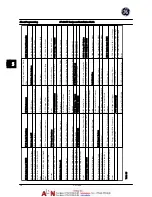
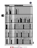
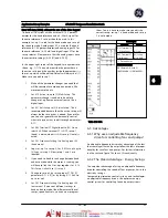
5
.8
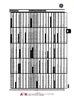
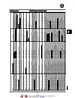
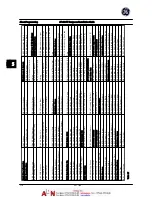
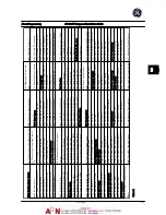
About Programming
AF-600 FP Design and Installation Guide
DET-768A
5-11
5
5
Summary of Contents for AF-600 FP Series
Page 1: ...AF 600 FPTM Fan Pump Drive Design and Installation Guide GE ...
Page 17: ...Introduction AF 600 FP Design and Installation Guide 1 10 DET 768A 1 1 ...
Page 39: ...Start Up and Functional Tes AF 600 FP Design and Installation Guide 3 6 DET 768A 3 3 ...
Page 57: ...About Programming AF 600 FP Design and Installation Guide 5 14 DET 768A 5 5 ...
Page 73: ...Application Set up Examples AF 600 FP Design and Installation Guide 6 16 DET 768A 6 6 ...
Page 83: ...Installation Consideration AF 600 FP Design and Installation Guide 7 10 DET 768A 7 7 ...
Page 87: ...Status Messages AF 600 FP Design and Installation Guide 8 4 DET 768A 8 8 ...
Page 97: ...Warnings and Alarms AF 600 FP Design and Installation Guide 9 10 DET 768A 9 9 ...
Page 101: ...Basic Troubleshooting AF 600 FP Design and Installation Guide 10 4 DET 768A 10 0 ...
Page 103: ...Terminal and Applicable Wir AF 600 FP Design and Installation Guide 11 2 DET 768A 11 1 ...


