

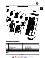
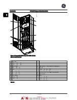
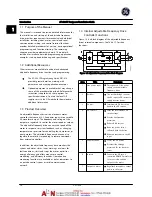

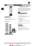
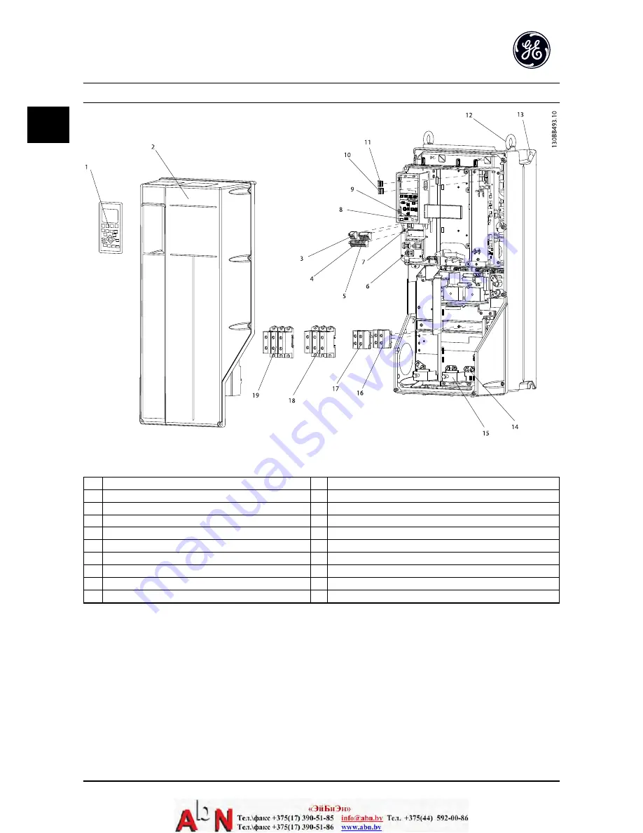
Figure 1.2 Exploded View Unit Sizes 15, 21, 22, 31, and 32
1
Keypad
11
Relay 2 (04, 05, 06)
2
Cover
12
Lifting ring
3
RS-485 serial bus connector
13
Mounting slot
4
Digital I/O and 24 V power supply
14
Grounding clamp (PE)
5
Analog I/O connector
15
Cable strain relief / PE ground
6
Cable strain relief/PE ground
16
Brake terminal (-81, +82)
7
USB connector
17
Load sharing terminal (DC bus) (-88, +89)
8
Serial bus terminal switch
18
Motor output terminals 96 (U), 97 (V), 98 (W)
9
Analog switches (A53), (A54)
19
Line power input terminals 91 (L1), 92 (L2), 93 (L3)
10
Relay 1 (01, 02, 03)
Table 1.2
Introduction
AF-600 FP Design and Installation Guide
1-2
DET-768A
1
1
Summary of Contents for AF-600 FP Series
Page 1: ...AF 600 FPTM Fan Pump Drive Design and Installation Guide GE ...
Page 17: ...Introduction AF 600 FP Design and Installation Guide 1 10 DET 768A 1 1 ...
Page 39: ...Start Up and Functional Tes AF 600 FP Design and Installation Guide 3 6 DET 768A 3 3 ...
Page 57: ...About Programming AF 600 FP Design and Installation Guide 5 14 DET 768A 5 5 ...
Page 73: ...Application Set up Examples AF 600 FP Design and Installation Guide 6 16 DET 768A 6 6 ...
Page 83: ...Installation Consideration AF 600 FP Design and Installation Guide 7 10 DET 768A 7 7 ...
Page 87: ...Status Messages AF 600 FP Design and Installation Guide 8 4 DET 768A 8 8 ...
Page 97: ...Warnings and Alarms AF 600 FP Design and Installation Guide 9 10 DET 768A 9 9 ...
Page 101: ...Basic Troubleshooting AF 600 FP Design and Installation Guide 10 4 DET 768A 10 0 ...
Page 103: ...Terminal and Applicable Wir AF 600 FP Design and Installation Guide 11 2 DET 768A 11 1 ...


