


1.1 Purpose of the Manual
This manual is intended to provide detailed information for
the installation and start-up of the adjustable frequency
drive. provides requirements for mechanical and electrical
installation, including input, motor, control and serial
communications wiring, and control terminal functions.
provides detailed procedures for start-up, basic operational
programming, and functional testing. The remaining
chapters provide supplementary details. These details
include user interface, detailed programming, application
examples, start-up troubleshooting, and specifications.
1.2 Additional
Resources
Other resources are available to understand advanced
adjustable frequency drive functions and programming.
•
The
AF-600 FP Programming Guide, DET-618
provides greater detail on working with
parameters and many application examples.
•
Optional equipment is available that may change
some of the procedures described. Reference the
instructions supplied with those options for
specific requirements. Contact the local GE
supplier or visit the GE website for downloads or
additional information.
1.3 Product
Overview
An adjustable frequency drive is an electronic motor
controller that converts AC line power input into a variable
AC waveform output. The frequency and voltage of the
output are regulated to control the motor speed or torque.
The adjustable frequency drive can vary the speed of the
motor in response to system feedback, such as changing
temperature or pressure for controlling fan, compressor, or
pump motors. The adjustable frequency drive can also
regulate the motor by responding to remote commands
from external controllers.
In addition, the adjustable frequency drive monitors the
system and motor status, issues warnings or alarms for
fault conditions, starts and stops the motor, optimizes
energy efficiency, and offers many more control,
monitoring, and efficiency functions. Operation and
monitoring functions are available as status indications to
an outside control system or serial communication
network.
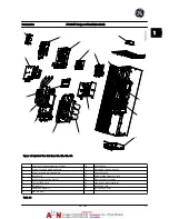
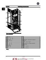
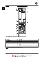
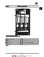
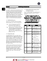
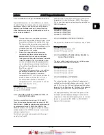
1.4 Internal Adjustable Frequency Drive
Controller Functions
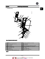
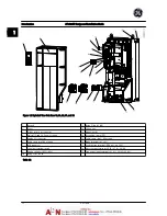
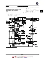
Figure 1.8
is a block diagram of the adjustable frequency
drive's internal components. See
Table 1.7
for their
functions.
Figure 1.8 Adjustable Frequency Drive Block Diagram
Area
Title
Functions
1
Line power input
•
Three-phase AC line power
supply to the adjustable
frequency drive
2
Rectifier
•
The rectifier bridge converts
the AC input to DC current to
supply inverter power
3
DC bus
•
Intermediate DC bus circuit
handles the DC current
4
DC reactors
•
Filter the intermediate DC
circuit voltage
•
Provide line transient
protection
•
Reduce RMS current
•
Raise the power factor
reflected back to the line
•
Reduce harmonics on the AC
input
5
Capacitor bank
•
Stores the DC power
•
Provides ride-through
protection for short power
losses
6
Inverter
•
Converts the DC into a
controlled PWM AC waveform
for a controlled variable
output to the motor
7
Output to motor
•
Regulated three-phase output
power to the motor
Introduction
AF-600 FP Design and Installation Guide
1-8
DET-768A
1
1
Summary of Contents for AF-600 FP Series
Page 1: ...AF 600 FPTM Fan Pump Drive Design and Installation Guide GE ...
Page 17: ...Introduction AF 600 FP Design and Installation Guide 1 10 DET 768A 1 1 ...
Page 39: ...Start Up and Functional Tes AF 600 FP Design and Installation Guide 3 6 DET 768A 3 3 ...
Page 57: ...About Programming AF 600 FP Design and Installation Guide 5 14 DET 768A 5 5 ...
Page 73: ...Application Set up Examples AF 600 FP Design and Installation Guide 6 16 DET 768A 6 6 ...
Page 83: ...Installation Consideration AF 600 FP Design and Installation Guide 7 10 DET 768A 7 7 ...
Page 87: ...Status Messages AF 600 FP Design and Installation Guide 8 4 DET 768A 8 8 ...
Page 97: ...Warnings and Alarms AF 600 FP Design and Installation Guide 9 10 DET 768A 9 9 ...
Page 101: ...Basic Troubleshooting AF 600 FP Design and Installation Guide 10 4 DET 768A 10 0 ...
Page 103: ...Terminal and Applicable Wir AF 600 FP Design and Installation Guide 11 2 DET 768A 11 1 ...


