


7.
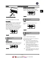
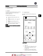
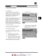
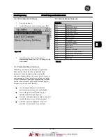
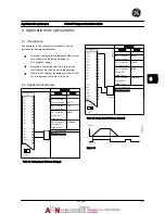
AN-15 Terminal 53 High Ref./Feedb. Value
. Set
maximum speed reference on Terminal 53 at 50
Hz. (This tells the adjustable frequency drive that
the maximum voltage received on Terminal 53
(10 V) equals 50 Hz output.)
Figure 5.7
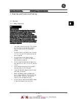
With an external device providing a 0–10 V control signal
connected to adjustable frequency drive terminal 53, the
system is now ready for operation. Note that the scroll bar
on the right in the last figure of the display is at the
bottom, indicating the procedure is complete.
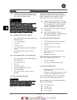
Figure 5.8
shows the wiring connections used to enable
this set-up.
Figure 5.8 Wiring Example for External Device Providing 0–10 V
Control Signal (Adjustable Frequency Drive Left, External Device
Right)
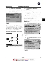
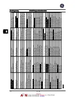
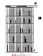
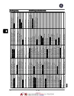
5.3 Control
Terminal Programming
Examples
Control terminals can be programmed.
•
Each terminal has specified functions it is capable
of performing.
•
Parameters associated with the terminal enable
the function.
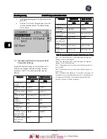
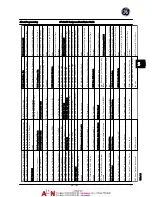
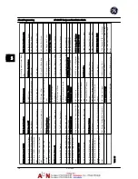
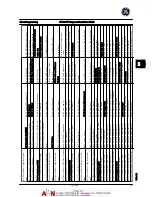
See
Table 2.4
for control terminal parameter number and
default setting. (Default setting can change based on the
selection in
K-03 Regional Settings
.)
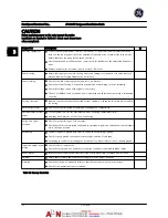
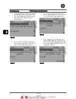
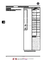
The following example shows accessing Terminal 18 to see
the default setting.
1.
Press [Main Menu] twice, scroll to and press [OK].
Figure 5.9
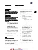
2.
Scroll to parameter group E-##
Digital In/Out
and
press [OK].
Figure 5.10
About Programming
AF-600 FP Design and Installation Guide
DET-768A
5-3
5
5
Summary of Contents for AF-600 FP Series
Page 1: ...AF 600 FPTM Fan Pump Drive Design and Installation Guide GE ...
Page 17: ...Introduction AF 600 FP Design and Installation Guide 1 10 DET 768A 1 1 ...
Page 39: ...Start Up and Functional Tes AF 600 FP Design and Installation Guide 3 6 DET 768A 3 3 ...
Page 57: ...About Programming AF 600 FP Design and Installation Guide 5 14 DET 768A 5 5 ...
Page 73: ...Application Set up Examples AF 600 FP Design and Installation Guide 6 16 DET 768A 6 6 ...
Page 83: ...Installation Consideration AF 600 FP Design and Installation Guide 7 10 DET 768A 7 7 ...
Page 87: ...Status Messages AF 600 FP Design and Installation Guide 8 4 DET 768A 8 8 ...
Page 97: ...Warnings and Alarms AF 600 FP Design and Installation Guide 9 10 DET 768A 9 9 ...
Page 101: ...Basic Troubleshooting AF 600 FP Design and Installation Guide 10 4 DET 768A 10 0 ...
Page 103: ...Terminal and Applicable Wir AF 600 FP Design and Installation Guide 11 2 DET 768A 11 1 ...


