


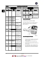

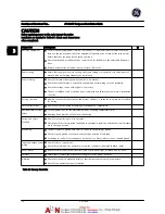


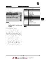


CAUTION
Before applying power to the unit, inspect the entire
installation as detailed in
Table 3.1
. Check mark those items
when completed.
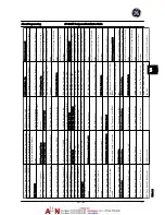
Inspect for
Description
☑
Auxiliary equipment
•
Look for auxiliary equipment, switches, disconnects, or input fuses/circuit breakers that may
reside on the input power side of the adjustable frequency drive or output side to the motor.
Ensure that they are ready for full speed operation.
•
Check function and installation of any sensors used for feedback to the adjustable frequency
drive.
•
Remove power factor correction caps on motor(s), if present.
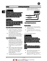
Cable routing
•
Ensure that input power, motor wiring, and control wiring are separated or in three separate
metallic conduits for high frequency noise isolation.
Control wiring
•
Check for broken or damaged wires and loose connections.
•
Check that control wiring is isolated from power and motor wiring for noise immunity.
•
Check the voltage source of the signals, if necessary.
•
The use of shielded cable or twisted pair is recommended. Ensure that the shield is terminated
correctly.
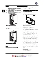
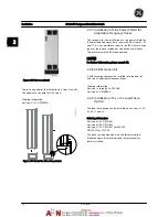
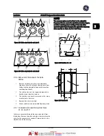
Cooling clearance
•
Measure to make sure that the top and bottom clearance is adequate to ensure proper airflow
for cooling.
EMC considerations
•
Check for proper installation regarding electromagnetic compatibility.
Environmental consider-
ations
•
See equipment label for the maximum ambient operating temperature limits.
•
Humidity levels must be 5%–95% non-condensing.
Fusing and circuit
breakers
•
Check for proper fusing or circuit breakers.
•
Check that all fuses are inserted firmly and in operational condition and that all circuit breakers
are in the open position.
Grounding
•
The unit requires a ground wire from its chassis to the building's ground.
•
Check for good ground connections that are tight and free of oxidation.
•
Grounding to conduit or mounting the back panel to a metal surface is not a suitable ground.
Input and output power
wiring
•
Check for loose connections.
•
Check that motor and line power are in separate conduits or separated shielded cables.
Panel interior
•
Inspect to ensure that the unit interior is free of dirt, metal chips, moisture, and corrosion.
Switches
•
Ensure that all switch and disconnect settings are in the proper positions.
Vibration
•
Check that the unit is mounted solidly or that shock mounts are used, as necessary.
•
Check for an unusual amount of vibration.
Table 3.1 Start-up Check List
Start Up and Functional Tes...
AF-600 FP Design and Installation Guide
3-2
DET-768A
3
3
Summary of Contents for AF-600 FP Series
Page 1: ...AF 600 FPTM Fan Pump Drive Design and Installation Guide GE ...
Page 17: ...Introduction AF 600 FP Design and Installation Guide 1 10 DET 768A 1 1 ...
Page 39: ...Start Up and Functional Tes AF 600 FP Design and Installation Guide 3 6 DET 768A 3 3 ...
Page 57: ...About Programming AF 600 FP Design and Installation Guide 5 14 DET 768A 5 5 ...
Page 73: ...Application Set up Examples AF 600 FP Design and Installation Guide 6 16 DET 768A 6 6 ...
Page 83: ...Installation Consideration AF 600 FP Design and Installation Guide 7 10 DET 768A 7 7 ...
Page 87: ...Status Messages AF 600 FP Design and Installation Guide 8 4 DET 768A 8 8 ...
Page 97: ...Warnings and Alarms AF 600 FP Design and Installation Guide 9 10 DET 768A 9 9 ...
Page 101: ...Basic Troubleshooting AF 600 FP Design and Installation Guide 10 4 DET 768A 10 0 ...
Page 103: ...Terminal and Applicable Wir AF 600 FP Design and Installation Guide 11 2 DET 768A 11 1 ...


