

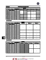


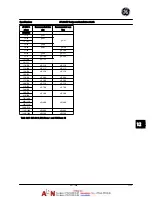


Control card, RS-485 serial communication
Terminal number
68 (P,TX+, RX+), 69 (N,TX-, RX-)
Terminal number 61
Common for terminals 68 and 69
The RS-485 serial communication circuit is functionally seated from other central circuits and galvanically isolated from the
supply voltage (PELV).
Digital output
Programmable digital/pulse outputs
2
Terminal number
27, 29
1)
Voltage level at digital/frequency output
0–24 V
Max. output current (sink or source)
40 mA
Max. load at frequency output
1 k
Ω
Max. capacitive load at frequency output
10 nF
Minimum output frequency at frequency output
0 Hz
Maximum output frequency at frequency output
32 kHz
Accuracy of frequency output
Max. error: 0.1% of full scale
Resolution of frequency outputs
12 bit
1) Terminal 27 and 29 can also be programmed as input.
The digital output is galvanically isolated from the supply voltage (PELV) and other high-voltage terminals.
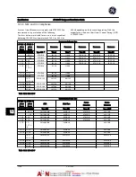
Control card, 24 V DC output
Terminal number
12, 13
Max. load
200 mA
The 24 V DC supply is galvanically isolated from the supply voltage (PELV), but has the same potential as the analog and digital
inputs and outputs.
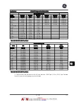
Relay outputs
Programmable relay outputs
2
Relay 01 Terminal number
1-3 (break), 1-2 (make)
Max. terminal load (AC-1)
1)
on 1-3 (NC), 1-2 (NO) (Resistive load)
240 V AC, 2 A
Max. terminal load (AC-15)
1)
(Inductive load
@
cos
φ
0.4)
240 V AC, 0.2 A
Max. terminal load (DC-1)
1)
on 1-2 (NO), 1-3 (NC) (Resistive load)
60 V DC, 1 A
Max. terminal load (DC-13)
1)
(Inductive load)
24 V DC, 0.1 A
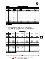
Relay 02 Terminal number
4-6 (break), 4-5 (make)
Max. terminal load (AC-1)
1)
on 4-5 (NO) (Resistive load)
2)3)
400 V AC, 2 A
Max. terminal load (AC-15)
1)
on 4-5 (NO) (Inductive load
@
cos
φ
0.4)
240 V AC, 0.2 A
Max. terminal load (DC-1)
1)
on 4-5 (NO) (Resistive load)
80 V DC, 2 A
Max. terminal load (DC-13)
1)
on 4-5 (NO) (Inductive load)
24 V DC, 0.1 A
Max. terminal load (AC-1)
1)
on 4-6 (NC) (Resistive load)
240 V AC, 2 A
Max. terminal load (AC-15)
1)
on 4-6 (NC) (Inductive load
@
cos
φ
0.4)
240 V AC, 0.2 A
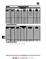
Max. terminal load (DC-1)
1)
on 4-6 (NC) (Resistive load)
50 V DC, 2 A
Max. terminal load (DC-13)
1)
on 4-6 (NC) (Inductive load)
24 V DC, 0.1 A
Min. terminal load on 1-3 (NC), 1-2 (NO), 4-6 (NC), 4-5 (NO)
24 V DC 10 mA, 24 V AC 20 mA
Environment according to EN 60664-1
overvoltage category III/pollution degree 2
1) IEC 60947 parts 4 and 5
The relay contacts are galvanically isolated from the rest of the circuit by reinforced isolation (PELV).
2) Overvoltage Category II
3) UL applications 300 V AC 2 A
Specifications
AF-600 FP Design and Installation Guide
12-14
DET-768A
12
2
Summary of Contents for AF-600 FP Series
Page 1: ...AF 600 FPTM Fan Pump Drive Design and Installation Guide GE ...
Page 17: ...Introduction AF 600 FP Design and Installation Guide 1 10 DET 768A 1 1 ...
Page 39: ...Start Up and Functional Tes AF 600 FP Design and Installation Guide 3 6 DET 768A 3 3 ...
Page 57: ...About Programming AF 600 FP Design and Installation Guide 5 14 DET 768A 5 5 ...
Page 73: ...Application Set up Examples AF 600 FP Design and Installation Guide 6 16 DET 768A 6 6 ...
Page 83: ...Installation Consideration AF 600 FP Design and Installation Guide 7 10 DET 768A 7 7 ...
Page 87: ...Status Messages AF 600 FP Design and Installation Guide 8 4 DET 768A 8 8 ...
Page 97: ...Warnings and Alarms AF 600 FP Design and Installation Guide 9 10 DET 768A 9 9 ...
Page 101: ...Basic Troubleshooting AF 600 FP Design and Installation Guide 10 4 DET 768A 10 0 ...
Page 103: ...Terminal and Applicable Wir AF 600 FP Design and Installation Guide 11 2 DET 768A 11 1 ...


