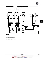


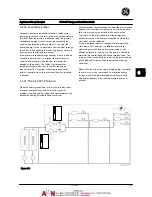
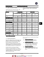


3.
Current transducers.
4.
Opto-coupler, brake module.
5.
Internal soft-charge, RFI and temperature
measurement circuits.
6.
Custom relays.
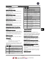
Figure 7.3 Galvanic isolation
The functional galvanic isolation (a and b in drawing) is for
the 24 V backup option and for the RS-485 standard bus
interface.
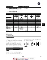
WARNING
Installation at high altitude:
380–480 V, unit size 1x, 2x and 3x: At altitudes above 6,600
ft [2 km], please contact GE regarding PELV.
380–480 V, unit size 4x, 5x and 6x: At altitudes above
10,000 ft [3 km], please contact GE regarding PELV.
525–690 V: At altitudes above 6,600 ft [2 km], please
contact GE regarding PELV.
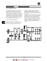
7.5 Derating
7.5.1 Purpose of Derating
Derating must be taken into account when using the
adjustable frequency drive at low air pressure (high
elevations), at low speeds, with long motor cables, cables
with a large cross-section or at high ambient temperature.
The required action is described in this section.
7.5.2 Derating for Ambient Temperature
90% adjustable frequency drive output current can be
maintained up to max. 122° F [50
°
C] ambient temperature.
With a typical full load current of EFF 2 motors, full output
shaft power can be maintained up to 122° F [50
°
C].
For more specific data and/or derating information for
other motors or conditions, please contact GE.
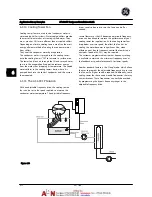
7.5.3 Automatic Adaptations to Ensure
Performance
The adjustable frequency drive constantly checks for
critical levels of internal temperature, load current, high
voltage on the intermediate circuit and low motor speeds.
As a response to a critical level, the adjustable frequency
drive can adjust the switching frequency and / or change
the switching pattern in order to ensure the performance
of the adjustable frequency drive. The capability to
automatically reduce the output current extends the
acceptable operating conditions even further.
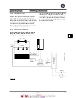
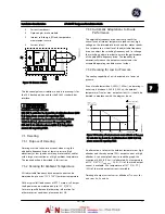
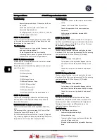
7.5.4 Derating for Low Air Pressure
The cooling capability of air is decreased at a lower air
pressure.
At an altitude lower than 3,300 ft [1,000 m], no derating is
necessary, but above 3,300 ft [1,000 m], the ambient
temperature (T
AMB
) or max. output current (I
out
) should be
derated in accordance with the diagram shown.
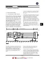
Figure 7.4 Derating of output current versus altitude at T
AMB, MAX
for unit sizes 1x, 2x and 3x. At altitudes above 6,600 ft [2 km],
please contact GE regarding PELV.
An alternative is to lower the ambient temperature at high
altitudes and thereby ensure 100% output current at high
altitudes. As an example of how to read the graph, the
situation at 6,600 ft [2 km] is elaborated. At a temperature
of 113° F [45°C] (T
AMB, MAX
- 3.3 K), 91% of the rated output
current is available. At a temperature of 107° F [41.7°C],
100% of the rated output current is available.
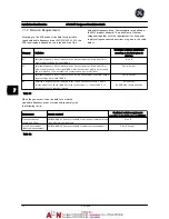
Derating of output current versus altitude at T
AMB, MAX
for
unit sizes 4x, 5x and 6x.
Installation Consideration
AF-600 FP Design and Installation Guide
DET-768A
7-7
7
7
Summary of Contents for AF-600 FP Series
Page 1: ...AF 600 FPTM Fan Pump Drive Design and Installation Guide GE ...
Page 17: ...Introduction AF 600 FP Design and Installation Guide 1 10 DET 768A 1 1 ...
Page 39: ...Start Up and Functional Tes AF 600 FP Design and Installation Guide 3 6 DET 768A 3 3 ...
Page 57: ...About Programming AF 600 FP Design and Installation Guide 5 14 DET 768A 5 5 ...
Page 73: ...Application Set up Examples AF 600 FP Design and Installation Guide 6 16 DET 768A 6 6 ...
Page 83: ...Installation Consideration AF 600 FP Design and Installation Guide 7 10 DET 768A 7 7 ...
Page 87: ...Status Messages AF 600 FP Design and Installation Guide 8 4 DET 768A 8 8 ...
Page 97: ...Warnings and Alarms AF 600 FP Design and Installation Guide 9 10 DET 768A 9 9 ...
Page 101: ...Basic Troubleshooting AF 600 FP Design and Installation Guide 10 4 DET 768A 10 0 ...
Page 103: ...Terminal and Applicable Wir AF 600 FP Design and Installation Guide 11 2 DET 768A 11 1 ...


