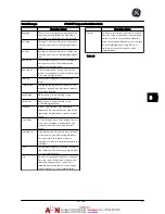


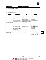
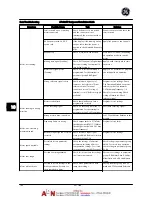


Symptom
Possible Cause
Test
Solution
Open power fuses or circuit
breaker trip
Phase to phase short
Motor or panel has a short phase
to phase. Check motor and panel
phase for shorts.
Eliminate any shorts detected.
Motor overload
Motor is overloaded for the
application.
Perform start-up test and verify
motor current is within specifi-
cations. If motor current is
exceeding nameplate full load
current, motor may run only with
reduced load. Review the specifi-
cations for the application.
Loose connections
Perform pre-startup check for loose
connections.
Tighten loose connections.
Line power current
imbalance greater than 3%
Problem with line power (See
Alarm 4 Line phase loss
description)
Rotate input power leads into the
adjustable frequency drive one
position: A to B, B to C, C to A.
If imbalanced leg follows the wire,
it is a power problem. Check line
power supply.
Problem with the adjustable
frequency drive
Rotate input power leads into the
adjustable frequency drive one
position: A to B, B to C, C to A.
If imbalance leg stays on same
input terminal, it is a problem with
the unit. Contact the supplier.
Motor current imbalance
greater than 3%
Problem with motor or motor
wiring
Rotate output motor leads one
position: U to V, V to W, W to U.
If imbalanced leg follows the wire,
the problem is in the motor or
motor wiring. Check motor and
motor wiring.
Problem with the adjustable
frequency drives
Rotate output motor leads one
position: U to V, V to W, W to U.
If imbalance leg stays on same
output terminal, it is a problem
with the unit. Contact the supplier.
Acoustic noise or vibration
(e.g., a fan blade is making
noise or vibrations at
certain frequencies)
Resonances, e.g., in the motor/fan
system
Bypass critical frequencies by using
parameters in parameter group
4-6*.
Check if noise and/or vibration
have been reduced to an
acceptable limit.
Turn off overmodulation in
F-38 Overmodulation
.
Change switching pattern and
frequency in parameter group
14-0*.
Increase Resonance Dampening in
H-64 Resonance Dampening
.
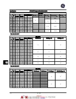
Table 10.1
Basic Troubleshooting
AF-600 FP Design and Installation Guide
DET-768A
10-3
10
10
Summary of Contents for AF-600 FP Series
Page 1: ...AF 600 FPTM Fan Pump Drive Design and Installation Guide GE ...
Page 17: ...Introduction AF 600 FP Design and Installation Guide 1 10 DET 768A 1 1 ...
Page 39: ...Start Up and Functional Tes AF 600 FP Design and Installation Guide 3 6 DET 768A 3 3 ...
Page 57: ...About Programming AF 600 FP Design and Installation Guide 5 14 DET 768A 5 5 ...
Page 73: ...Application Set up Examples AF 600 FP Design and Installation Guide 6 16 DET 768A 6 6 ...
Page 83: ...Installation Consideration AF 600 FP Design and Installation Guide 7 10 DET 768A 7 7 ...
Page 87: ...Status Messages AF 600 FP Design and Installation Guide 8 4 DET 768A 8 8 ...
Page 97: ...Warnings and Alarms AF 600 FP Design and Installation Guide 9 10 DET 768A 9 9 ...
Page 101: ...Basic Troubleshooting AF 600 FP Design and Installation Guide 10 4 DET 768A 10 0 ...
Page 103: ...Terminal and Applicable Wir AF 600 FP Design and Installation Guide 11 2 DET 768A 11 1 ...


