1586A
Users Manual
4-12
•
For the
Alarm
trigger type: The scan sweep is triggered by an alarm that has
tripped. To do this, select the Alarm trigger type in the test setup and assign a
channel to be a trigger. When the scan is started, the Product automatically starts
to monitor the channel set as the trigger for a tripped alarm. Once an alarm is
tripped, the scan sweep starts and runs as directed by the test setup. Scan sweeps
will continue as long as the alarm is tripped. If the alarm is no longer tripped, the
Product will finish the scan in progress then wait for next alarm trip.
a.
Configure the applicable channel alarm as previously described.
b.
Push
then push
to start the scan.
•
For the
Manual
trigger type: Push
to start the scan. The scan performs one
scan cycle then stops. Push
again to trigger another scan cycle. At any
time, push
again to stop the test or push
to pause the test. If automatic
recording is set to OFF, push
to record data.
•
For the
Automated Test
trigger type: Push
then push
to start the
test. The Product reads the setpoint information and automatically starts a scan
sweep when the setpoint parameters (Setpoint, Tolerance, Stability, and
Soaktime) are met. If the Control Source parameter is set to On and the Product
is connected to an external temperature source, the Product sets the temperature
without the need for the user to do so. The scan repeats for the amount of times
set in the Scan Count setting at each setpoint.
View Scan Data and Statistics
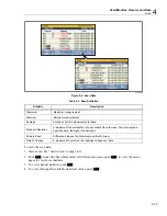
The Scan Data feature lets the user see the scan data from the last scan sweep (see
Figure 4-4). This feature is located in the Scan menu (push
then push
). The
data on this menu updates in real-time. From the Scan Data menu, the user can open a
Statistics menu to view minimum, maximum, average, and standard deviation statistics
for each channel (see Table 4-3).
If Mx+B is applied to the channel, an [Mx+B] icon will show next to the channel
number. If an alarm is tripped, the alarm number will show next to the channel as a red
icon and also the measurement value will be red. See Figure 4-4.
Summary of Contents for 1586A
Page 6: ...1586A Users Manual iv Error Messages 7 3 Troubleshooting 7 20...
Page 8: ...1586A Users Manual vi...
Page 10: ...1586A Users Manual viii...
Page 34: ...1586A Users Manual 2 2...
Page 42: ...1586A Users Manual 2 10 2 3 4 1 hcn018 eps Figure 2 6 Relay Card Installation...
Page 44: ...1586A Users Manual 2 12 hcn032 eps Figure 2 7 DAQ STAQ Multiplexer Installation...
Page 46: ...1586A Users Manual 2 14...
Page 48: ...1586A Users Manual 3 2...
Page 82: ...1586A Users Manual 3 36...
Page 84: ...1586A Users Manual 4 2...
Page 108: ...1586A Users Manual 5 2...
Page 114: ...1586A Users Manual 6 2...
Page 118: ...1586A Users Manual 6 6...
Page 120: ...1586A Users Manual 7 2...

