Error Messages and Troubleshooting
Error Messages
7
7-11
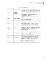
Table 7-1. Error Messages (cont.)
Error Code
Error Message
Causes and Solutions
Error 415
Module not
connected
Cause:
The Instrument attempted an operation but detected
that a required Input Module was not installed. This error can
also occur if a setup file is loaded without all the Input
Modules installed that the setup file requires.
Solution:
Install the required Input Module and try the
operation again. See Chapter 2.
Error 416
Channel unavailable
Cause:
The channel is unavailable or reserved for 3-wire or
4-wire use.
Solution:
Reconfigure the channel that reserved this sense
channel for use. See Chapter 3.
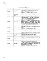
Error 417
Active module
disconnected
Cause:
An Input Module was disconnected. If a scan is was
in progress, it will be stopped.
Solution:
Install the Input Module again then try the test
again. If the Input Module was installed when the error
occurred, make sure the Input Module is fully seated in the
rear panel. See Chapter 2.
Error 418
Monitor state is
locked
Cause:
Monitor channel or monitor state is changed while an
alarm trigger scan or automated test is in progress.
Solution:
Stop the scan.
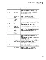
Error 419
Read config file failed
Cause:
The Instrument could not read the configuration file
that contains all the Instrument settings. When this happens,
the configurations are reset to factory defaults until the
configuration can be read again.
Solution:
Contact Fluke. See Chapter 1.
Error 420
Not a math channel
Cause:
Error occurs when a user attempts to set a math
channel on any channel other than Ch501 through Ch520.
Solution:
Check the parameter value and try again.
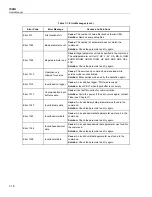
Error 421
Not a DIO channel
Cause:
Error occurs when a user attempts to set a DIO
channel on any channel other than Ch401.
Solution:
Check the parameter value and try again.
Summary of Contents for 1586A
Page 6: ...1586A Users Manual iv Error Messages 7 3 Troubleshooting 7 20...
Page 8: ...1586A Users Manual vi...
Page 10: ...1586A Users Manual viii...
Page 34: ...1586A Users Manual 2 2...
Page 42: ...1586A Users Manual 2 10 2 3 4 1 hcn018 eps Figure 2 6 Relay Card Installation...
Page 44: ...1586A Users Manual 2 12 hcn032 eps Figure 2 7 DAQ STAQ Multiplexer Installation...
Page 46: ...1586A Users Manual 2 14...
Page 48: ...1586A Users Manual 3 2...
Page 82: ...1586A Users Manual 3 36...
Page 84: ...1586A Users Manual 4 2...
Page 108: ...1586A Users Manual 5 2...
Page 114: ...1586A Users Manual 6 2...
Page 118: ...1586A Users Manual 6 6...
Page 120: ...1586A Users Manual 7 2...


