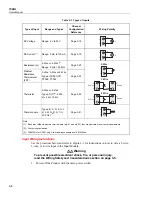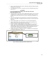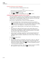
Input and Channel Configuration
Channel Configuration
3
3-21
Thermocouple Channels
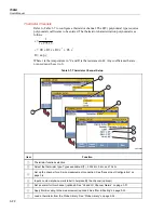
Refer to Table 3-6 to configure a thermocouple channel. Thermocouple types R and S
have optional correction polynomial coefficients to be entered. The correction equation is
as follows:
3
2
3
2
1
0
t
C
t
C
t
C
C
V
+
+
+
=
Δ
where
t
is the temperature in °C and
Δ
V
is the correction in millivolts. If the correction is
not used, leave the coefficients set to 0.
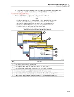
Table 3-6. Thermocouple Channel Configuration
1
2
3
4
5
6
hcn009.eps
Item Function
Thermocouple function selection.
Select the thermocouple type.
Input a custom alpha-numeric label to help identify the channel (optional).
Set an alarm for this channel (optional). See “HI and LO Channel Alarms” on page 3-31.
Apply Mx+B scaling to the measurement (optional). See “Mx+B Scaling” on page 3-30.
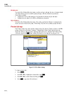
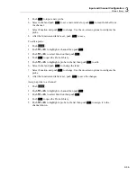
Load a thermocouple from the Probe Library. See “Probe Library” on page 3-34.
Summary of Contents for 1586A
Page 6: ...1586A Users Manual iv Error Messages 7 3 Troubleshooting 7 20...
Page 8: ...1586A Users Manual vi...
Page 10: ...1586A Users Manual viii...
Page 34: ...1586A Users Manual 2 2...
Page 42: ...1586A Users Manual 2 10 2 3 4 1 hcn018 eps Figure 2 6 Relay Card Installation...
Page 44: ...1586A Users Manual 2 12 hcn032 eps Figure 2 7 DAQ STAQ Multiplexer Installation...
Page 46: ...1586A Users Manual 2 14...
Page 48: ...1586A Users Manual 3 2...
Page 82: ...1586A Users Manual 3 36...
Page 84: ...1586A Users Manual 4 2...
Page 108: ...1586A Users Manual 5 2...
Page 114: ...1586A Users Manual 6 2...
Page 118: ...1586A Users Manual 6 6...
Page 120: ...1586A Users Manual 7 2...


